frosted.coot.scoot said:
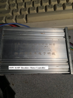
Indeed I do have a link for the controller I purchased. Here it is.
https://www.amazon.com/dp/B08J7Y9QQ8?psc=1&ref=ppx_yo2ov_dt_b_product_details
<snip>
There is not really any support info from Amazon where I bought the controller. There is no instructions that come with the controller.
Based on this picture
![51REkOK-rsL._AC_SL1000_[1].jpg](https://endless-sphere.com/sphere/data/attachments/179/179708-c2b31328169b4b7efcd3454300af00cc.jpg "51REkOK-rsL._AC_SL1000_[1].jpg")
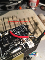
It must have a throttle input, since it specifies a throttle voltage range. The usual connector for this will have red for 5v, black for ground, and green for throttle signal, whcih match one of the connectors on this controller.
I see a pair of white wires with matching connectors; these are the self-learn. If you haven't already used that function, you will want to do so to make sure the phase/hall combination is correct for the motor so it operates correctly. (this won't have anything to do with the throttle behavior you get, however). If you've already done this, skip to the next section.
The other wiring I see looks typical of controllers of this type, so we can work that out if it is needed for other functions.
I I have found out a few things relating to the first post or two that I made concerning the charging port and battery output voltage. I now know how and where to connect to the charging port of the scooter. I also got the battery to start outputting its correct voltage by performing a bypass on the BMS as demonstrated ina video I found that directly deals with the Bird 2 scooter. After soldering a bridge between B+ and P+,
I got the correct output voltage frm the battery pack. SO those two posts are now answered as I see it.
Interesting that it has a B+ / P+; typically a BMS does not have any + connections other than the B+ that is the most positive wire of the balance connector (not typically marked as such). Usually it requires bypassing from B- to P- (and C- if there is a separate charging port) to get around a nonworking BMS. So this one is a nontypical design.
If you have to bypass the BMS to get voltage out, it usually means that one of the cell groups has a problem, and so the BMS has shutdown to prevent further damage to them that could lead to a fire. But since this is a custom BMS, it could just be a blown internal fuse on the BMS (other side of the board from the picture, most likely, if so). Or because these are rental scooters, it could be that this BMS has an extra cable that goes to the original controller or display that requires communication between them to enable it's output, or extra electronics in it that wirelessly communicate with something (phone, display, charging station, etc) to enable it.
In the latter case you'd just need to replace the BMS to protect the cells during use and charge. The instructions on the Bird website lead to this possibility:
To start your ride, scan the Bird’s QR code with your app.
because *something* on the scooter must have a wireless connection to the phone to talk to the app for this to work to turn it on and off. The BMS is a logical enough place for this to be, since it would turn all power on and off.
In the former cases you'd want to test things to make sure there isn't a problem. If you don't know which is the case, then testing is a good idea for future safety.
What are the individual cell group voltages, measured at the BMS balance connector at the BMS board itself, starting at the most negative up to the most positive?
That will tell you what the BMS sees, which helps you find the problem. If the voltages there are all correct, the BMS itself is probably just defective, and needs to be replaced.
If the voltages are not correct, then measure them at the cells themselves, which will tell you if the cells are the problem, or the balance wires.
If a cell is the problem, then depending on it's voltage, it may be safe to manually recharge, or you may need to replace it to prevent future risk of catastrophic failure.
I am now moving on to the issue that I am having which is that I am suppose to have a variable throttle, but after wiring the throttle to the controller I have some unexpected results. I thought the throttle was supposed to be the potentiometer type where the amount of throttle signal given to the motor is directly proportional to the amount of downward pressure your thumb places on the throttle lever. What I experience here is that the motor starts turning when I first depress the throttle lever to the full downward position. The wheel starts rotating at full throttle and even continues if the throttle lever is let to come back to its starting position. The motor will stay engaged at maximum until the throttle lever is once again depressed to the full throttle position.
I can't think of anything on a normal controller and throttle that would cause this to work that way, regardless of wiring correctly or not, etc.
But if the throttle itself is not a variable-voltage output, and is instead functioning as a toggle switch inside, it would. The instructions on the Bird website lead to this possibility:
Hit the throttle on the right to go and pull the brakes to slow.
If you measure the voltage at the throttle signal, from the signal wire to ground or battery negative, what does it read during the whole travel of the throttle?
If it only reads two set voltages, and not variable, you'll need to replace the throttle with a different one, such as one of these:
https://www.amazon.com/s?k=scooter+throttle&ref=nb_sb_noss_2
I've used this specific type
https://www.amazon.com/Universal-Throttle-Control-Electric-Scooters/dp/B07KK145CK/ref=sr_1_9?keywords=scooter+throttle&qid=1650824703&sr=8-9
from Grin Tech; it's decent enough as responsiveness goes, if you like thumb throttles.
If you want a lever throttle, I couldn't find one in a few minutes' search. A cable-brake lever can be used for one, though, by using a cable-operated-throttle body like this:
https://www.aliexpress.com/item/32954909008.html?spm=a2g0o.order_list.0.0.4f7f1802jVsCNo
pulled by the cable from the lever (which can be basically any brake lever that fits on your handlebar other than the one you already have for your brake, since you need that one
")
).
Note that if the brake lever doesn't pull the full rotation of the throttle, it won't give you full power/speed, only that up to the point the rotation stops. You can adjust the cable tension on the lever so that just a touch on the lever starts the motor moving, and that gives the best response range, but it still has to be adjusted so the motor is never moving unless you are actually pulling it.
I use that exact throttle unit for my SB Cruiser trike, in two places (one pulled by a brake lever for variable regen braking on a controller capable of that, and one pulled by an ATV thumb lever for throttle control on the times I need a throttle, since SBC is controlled via pedals most of the time).
Since you do get response from the system, you probably already ahve the wiring correct, but just in case:
The throttle wiring color for the old controller (black, red, blue) is not typical, but that may not mean anything. If it uses a normal hall throttle, then the one that is on the scooter should still work wtih your new controller. If the throttle itself has the same wire colors, my first guess would be red positive, black ground, and blue signal, but this is not necessarily the case.
If you can still power on the old controller, you can measure that connector for where it's 5v wire is, and ground you can verify by measuring continuity or ohms from each wire to the battery negative wire of the old controller while the controller is not connected to anything else. The signal is then the remaining wire.