Headway Pack Builders thread

frodus

10 kW
Joined
Mar 3, 2008
Messages
820
Location
Portland, OR
So, commence discussions on pack building for the Headway cells.

For Fechter Goodrum BMS issues/discussion/troubleshooting go here:
http://endless-sphere.com/forums/viewtopic.php?f=14&t=13380&p=200080&hilit=+30+headway#p200080


Lets start off by letting everyone know the pack configuration, number of cells, Watt-Hours, Voltage and Ah (so others can reference) and what its going into.

My setup: 32 in series, 6 in parallel for a total of 192 cells, 6144Wh, 102.4V, 60Ah
(if headway's claims are true of the 5C cont, 10C peak and 15C pulse.... that'd be 300A continuous, 600A peak with a 900A pulse)

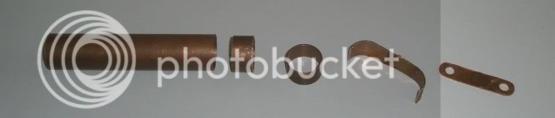
It will look a lot like this:
ttxgp-kingston-university-naked.jpg


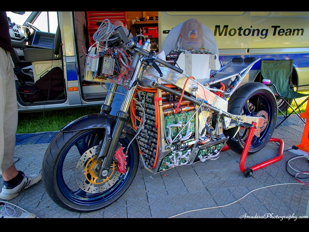
They're going in this:
normal_IMG_1585.jpg
 
OH, so much fun frotus. It must be hell having a day job. Tks for the kickoff.

My needs are ever so simple. Two 36/10 packs, BMS protected. Can be use separately or parallel together.
 
I'm doing a 72V pack, but not sure of AH yet (I have 230 cells, I might buy a few more to make it an even 240)... So, basically, looking at 24S x 10P (or is that 10P x 24S? I can never remember the proper syntax...)

But, there's still the chance that I may go with higher voltage, so nothing in stone yet... Just the fact that I'm using a buncha headways which are all stacked up in boxes in my laundry room... :twisted:

Chaster
 
Two 36/10's with headway BMS, another 36/10 in reserve (or maybe a BMSsed 36 20). I will use red cedar boards for construction, a traditional battery material.
 
dak664 said:
Two 36/10's with headway BMS, another 36/10 in reserve (or maybe a BMSsed 36 20). I will use red cedar boards for construction, a traditional battery material.

Wood's electrical resistance drops significantly if it gets wet... just something to keep in mind
 
I'll find out, although I am more worried about moisture in the controller and motor. Cedar has the property of being dry even when fresh cut, and does not absorb moisture so is relatively unaffected by humidity. Nowadays man-made materials are used but in the early days cedar breadboards made for consistent operation of radio circuits. Professional laboratory resistance boxes, etc. were also made from it; cheaper ones used shellac.
 
Thanks for the Cedar wood tip, dak664. I used treated wood for my frankenbox, but had planned to go to MDO or MDF to mount my Fatpacks. Cedar may be a better choice. They use MDO for roadsigns so it too should hold up!
otherDoc
 
What is being used for the strapping to connect the cells together ? I guess it would have to be copper since the BMS leads need to be soldered to it.
 
I bought a 10 foot roll of 3/4 inch "Master Plumber Copper pipe strapping" a while back and finally opened it up...what a ripoff, it is copper plated steel. They didn't even bother to plate the edge that was against the packaging cardboard, just what was visible through the front plastic. Take a magnet with you when shopping! It would be way too stiff, don't know about solid copper though, which could be annealed dead soft.

Fortunately I found a builders supply that had an old roll of 1 pound copper flashing. $90 for 20 feet of 20 inch wide, about $3 a pound. I plan on pressing and annealing a U in the straps for strain relief. Not sure how stiff it would become if I solder to the U. I have some #8 toothed lugs for the BMS, but unfortunately most of the teeth need reaming away to fit on the Headway screws.
 
I bought six feet of 3/4 inch copper pipe, used a sabre saw to cut sections, tin snips and pliers to open the pipe, and a hammer to flatten the sections. Idea and picture stolen from HAL9000v2.0: http://www.endless-sphere.com/forums/viewtopic.php?f=14&t=10220&p=171445&hilit=+brass#p159554

copperbars.jpg


I cut some of the sections into larger squares, similar to the ones you see on some of the prebuilt 48v Headway packs. Between cutting and flattening the pipe, deburring and grinding the sharp corners off, and drilling the holes, this method was more work than I expected. On the plus side, it only cost me about ten bucks for two 48V 20Ah packs. Still, I might recommend using some other solution unless money's really tight.
 
Over the past year or so I have been buying 1/2" and 1" copper strap from ebay ID metallectric for pretty cheap. He also sold it in 2" varieties, I don't see he has any listed at the moment, but if you contact him he might be able to set you up with a 25' or 50' roll. As you can see from the pics below, you can stack about 6 layers tall and drill through it pretty easily with an Ace Hardware cobalt drill and some oil.

The pics below are from way back in Feb/March, but what they hey some folks might not have seen it and maybe you'll get some ideas.

Tested Cells
file.php


Raw copper strap - this is the 1", I actually used 1/2" for the supercell row joiners, since they only carry about 20a charge current
file.php


Joiners drilled, ready to be re-flattened on each end.
file.php


Bare metal joiners - note there is a FUSE on each charge lead right where it leaves the cell joiner.
I don't see enough folks putting fuses here. On my xtracycle pack I had two charging wires short against each other. They immediately melted the jackets of all the other charging wires, and then all the cells shorted against each other. I was in my workshop so I managed to fight through the smoke and clip all the leads at the cells, but if it had been on my bike the whole thing would have gone up in flames. LifePO4 is inert, but the energy from a short is not.
file.php


WARNING - short potential between negative terminal and the silver ring that is the end of body, which is positive. If the cells twist relative to each other, your strap could be a hazard - put heavy duty shrinkwrap here:
file.php


Finished supercell joiners with fuse and short protection
file.php


30s8p Pack - series cells are joined by set-screws
file.php
 
Well, here is my first try. A 1-1/2 inch hole saw is perfect; one layer of mailing tape makes a tight fit (not that the fit should be that tight(?), but the labels had to pass through. The oak jig for making the straps from one pound copper flashing is shown, it clamps in a vise and the holes guide a 1/4 inch drill. I tinned them with a torch but need to get a hotter soldering iron as 60 watts will barely tack the BMS wires. Note the 9 amp polyfuse, I will add more in parallel after testing is complete. A dovetailed box with sliding covers is an obvious choice if that would provide enough cooling. Any vents would have to be on the side which is good because there is nothing there to short.

My 42 volt charger cuts out at 41.8 volts, not enough to activate any bypasses. I guess the charging voltage should be around 45 volts? Is 48 too much?
 

Attachments

  • Headway_36Volt_10AH_battery_pack.jpg
    107.3 KB · Views: 3,741
  • Headway_36Volt_10AH_battery_pack_detail.jpg
    95.1 KB · Views: 3,705
for 12S you should be able to use 43.8V to charge.

cooling is not a problem. i don't think you needed such heavy conductors. even 12G wire would handle the current in max discharge around 5C of 50A since it would only be for a few minutes anyway.

none of my luglockwashers were large enuff. that is a big screw!
 
Dennis, max charge for these cells is 3.65V a cell .... read the datasheet, don't tell people to overcharge their batteries. The charger should peak at 43.8V for a 3.65V/cell charge. The BMS will balance them as needed.

Also, the larger the conductor, the lower the voltage drop/losses. Bigger IS better. if you have it, use it.
 
The strap ends were sized to make contact with all the surface area of the stud, with some leeway for the quarter inch hole. Necking the center would be better, more flexible and easier to solder, but difficult to do with big scissors.

I scrounged two isolated 24 volt power supplies, in series they put out 54 volts. Is that too much for the Headway BMS? They are not current limited and the fuses will blow at 8 amps, so I guess I need a big 5 or 10 ohm resistor. Does the BMS do any charge current limiting?
 
anything over 3.65V a cell is TOO MUCH, so you'll have to figure out how to adjust lower.

read the datasheet on the cells:
www.evfr.net/uploads/headway/38120S.pdf

Why people are charging higher than this, I don't know.

Feel free, but you're on your own if there's a dead cell.
 
I was hoping the BMS would cut charging when all cells reached max voltage. Any hope on getting a schematic for it?

It pays to scrounge quality junk :)
There is a 24 volt adjustment that goes all the way down to 21. I've set it to 43.7, and am charging at 0.5 amps through 5 ohms. If I short the resistor the current goes to 5 amps. Is there a recommended charging current?

I am not one to push cell voltages, in fact I'd like to drop the max to 3.5 if that is possible. One way of interpreting the spec'd max of 3.65+/-0.05 would be a 3.60 limit!

Update: Current is now 130 ma and dropping slowly, most cells at 3.65 and the others coming up. BMS never got warm.
 
they will, but you're using power supplies, not chargers. Power supplies regulate the voltage. Chargers go constant current and slowly rise in voltage, then go constant voltage. BMS will cut out when all cells reach max, it'l cut out the charger. I bet it'd cut out immediately.

You don't have to charge the cell to 3.65V, just don't go OVER that.


NOTE TO EVERYONE:
Read the DATASHEET... all the max charge voltage and max charging current is there. I posted it, read it.
 
frodus said:
You don't have to charge the cell to 3.65V, just don't go OVER that.

My single cell LiFePO4 charger stops at 3.60V, FWIW. I could probably get pack a few more milliamp-hours in there by charging to 3.65V but I bet it wouldn't be a very noticeable difference.
 
chaster, I got a charging algorithm on its way for my 32s6p pack, I'll ask him to change it for your 72V charger as well.

then we can have a "charger programming party"... lol
 
All balanced now except for the one low cell at 3.41 I threw in as an experiment (it got shorted briefly). The optimum charging current would depend less on the cell than on the BMS (BTW there are two values for max charging current in that spec sheet, 20A and 150A) as it can only bypass so much current around fully-charged cells. Those 20 ohm resistors would seem to limit safe endpoint charging current to somewhere around 150 ma. A voltage regulated power supply with a series resistor mimics a current-limited battery charger, albeit not as efficiently and requiring more monitoring and an assortment of high wattage resistors. At 43.7 volts It was doing fine with a 5 ohm resistor at 130 ma, but shorting the resistor passed 250 ma because of the low cell, which raised all the charged cells to 3.8 volts (briefly). It would probably have been ok if one cell was not so low. But it would appear, with that BMS if one cell goes bad and you charge at a couple of amps for a long time the rest will be toast too.
 
frodus said:
chaster, I got a charging algorithm on its way for my 32s6p pack, I'll ask him to change it for your 72V charger as well.

then we can have a "charger programming party"... lol

Woohoo! Thanks Frodus.
 
It wasn't hard to swap the high cells among the two packs to get one with 3.65 volts everywhere, pulling 20 ma at a 43.8 volt power supply setting. The 27 amp polyfuses came in handy when one copper strap rotated to another. Having them at the end is good because any short crossing the strings on one side will go through them.

Don't see any reason to bump the charging voltage up enough to trip the BMS on a balanced pack. A short ride discharged them a little, 39.6 volts after about a kilometer. Satchel weighs in at 7 kg compared to 11 kg for three 12AH SLABs in the satchel. The wood extensions are to absorb some energy in a tipover, common along the roadside where kickstands are dicey. If there are no thermal issues the next case will be smaller I think, with styrofoam packing.

I plan to bring out a ribbon cable with the sense voltages through resistors to monitor the cell voltages without taking covers off. 1K resistors would drop my cheap multimeter readings down by 0.1 volt.
 

Attachments

  • Fully charged.jpg
    33.2 KB · Views: 4,631
  • Ready to go.jpg
    91 KB · Views: 4,632
Back
Top