CellLog 8S Alarm Circuit For Newbies

Joined
Aug 16, 2009
Messages
300
For several weeks now I have been trying to wrap my mind around the several threads showing how to do an alarm circuit for the CellLog voltage monitors. Maybe it's been because of the pain meds I was taking, or maybe I'm just too dense, but I couldn't figure out how to make one that worked without blowing out my CellLog.

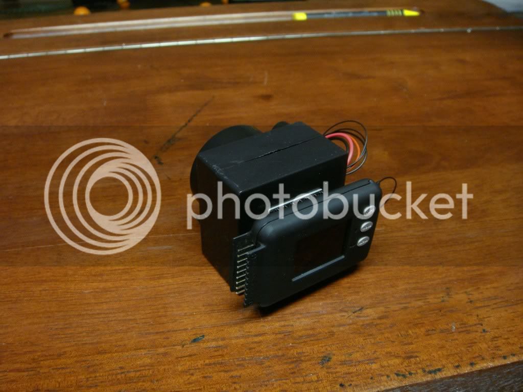
With the detailed help from Knoxie, I finally got an alarm circuit up and running, and it actually works great! I'm using this alarm to let me bulk charge my Headway packs up to almost top level. I have the alarm set to where it actuates at 3.60v. When I hear the loud buzzer go off, I know it's time to remove the bulk charger, and finish charging with my voltphreak array. That way, I insure that all cells are balanced and topped off, without having to use the array for hours at a time to charge the entire pack.

If you can use a solder iron, you can make this alarm circuit. I'm going to include the schematic that Knoxie made, and also include the parts list he provided. All the credit for this alarm circuit goes to him, in as much as he provided me with the information. Maybe he got the info somewhere else, but all I know is without his help, I would still be in the dark. So, hopefully this will help others who are scratching their head and wondering how to make one.

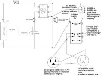
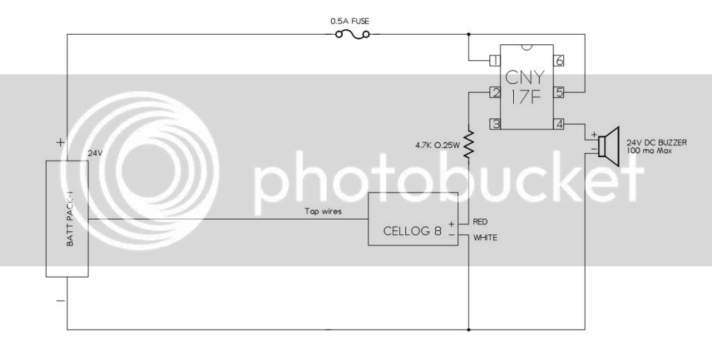
Here is the schematic showing how things go together:
schematic.jpg


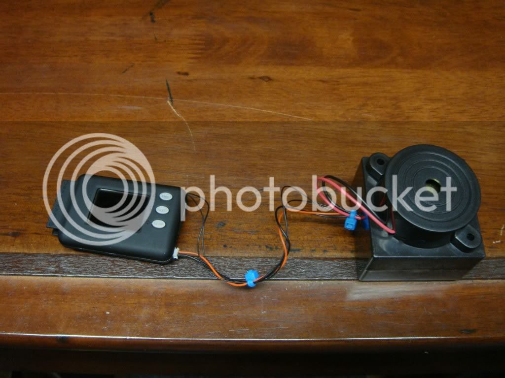
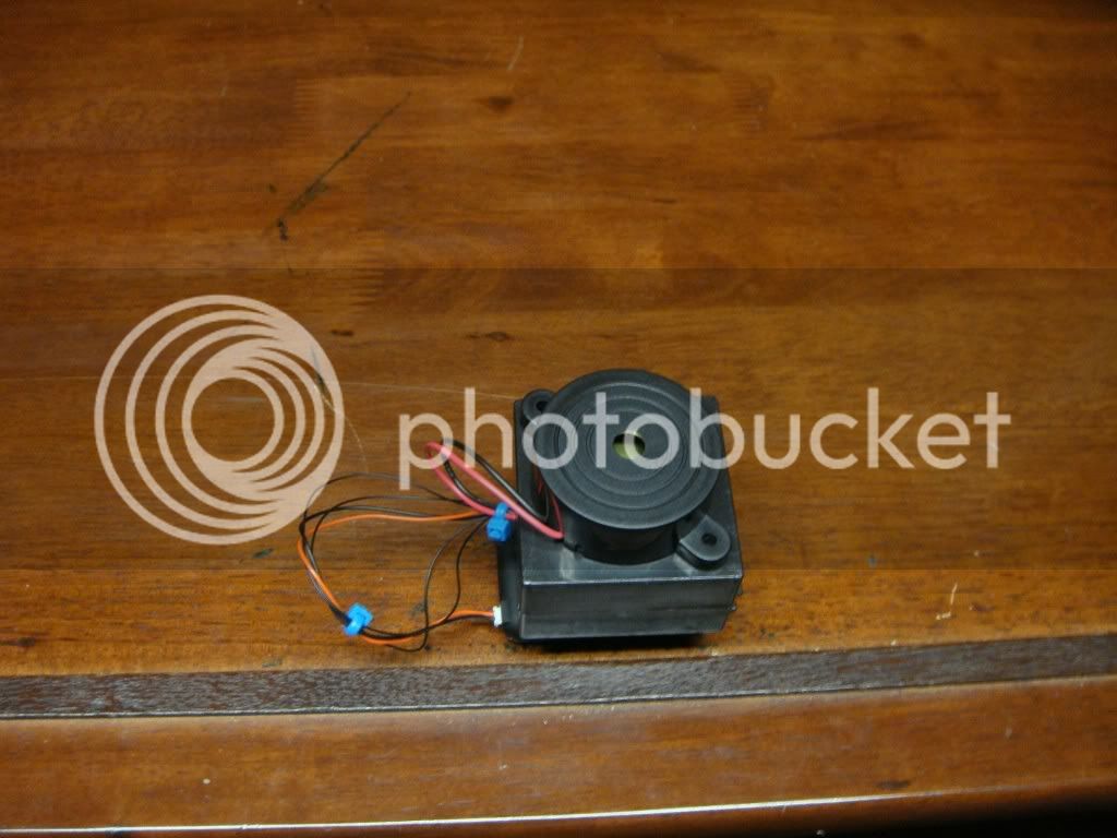
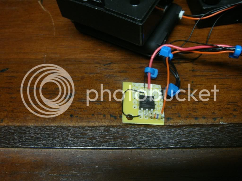
Here are some photos of how my efforts turned out:
01.jpg

02.jpg

03.jpg

04.jpg


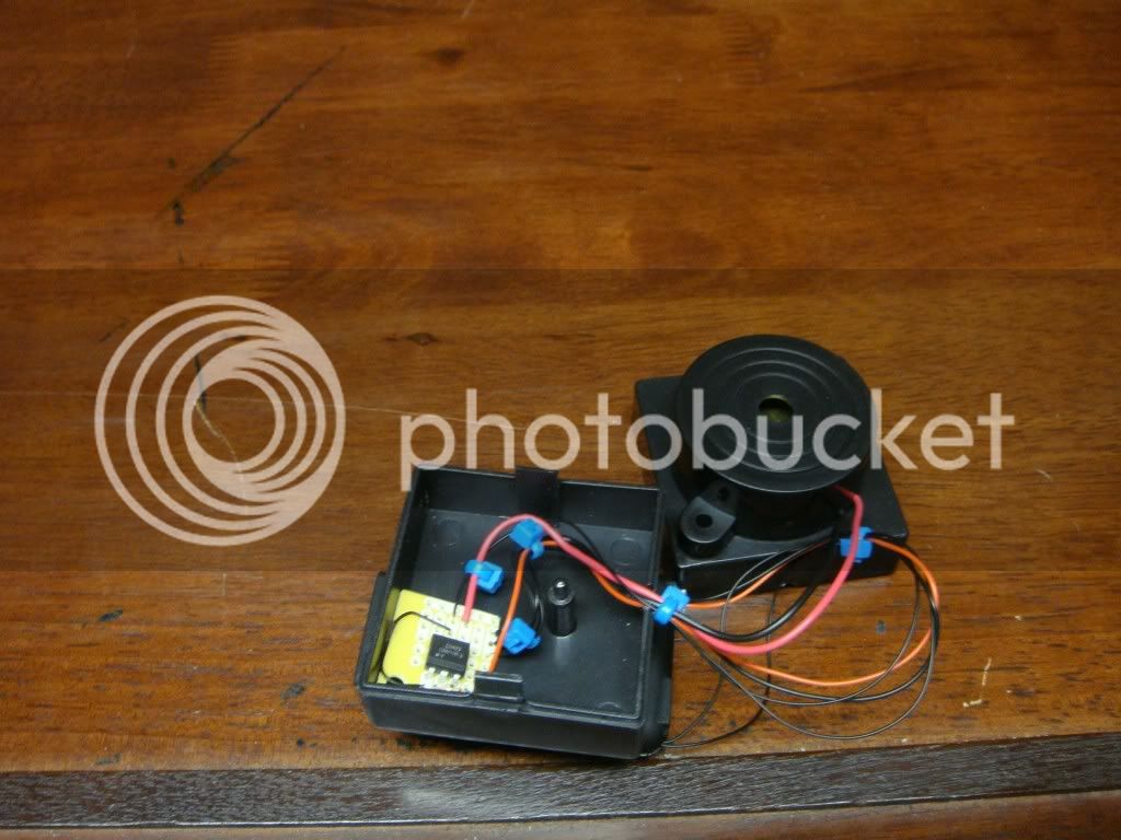
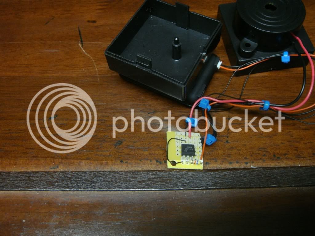
I think there is a limit to how many photos I can use in one post, so I'll continue this in the next one.

TJG
 
The rest of the photos:

05.jpg

06.jpg

07.jpg


I used a small plastic box I picked up from somewhere, and I altered the schematic a bit. I wanted to be able to use this on all my packs, so instead of tapping into the Positive and Negative leads out of the battery pack, I opened up the CellLog and tapped into pins 1 which is Negative and pin 9 which is Positive. That way I can now plug this alarm unit into the balance lead coming from the pack, while the bulk charger is plugged into the bulk charger connector.

Here is the parts list, again provided by Knoxie:

You can get the parts from pretty much anywhere, you need a piezo buzzer for 24V current limit is 100ma.

Wise to fit a fuse, you can fit these fuses in the wire or on the board with board mounting fuse holders.

Heres a typical buzzer

http://www.radioshack.com/product/index.jsp?productId=2062399

The resistors

http://www.radioshack.com/product/index.jsp?productId=2062346

The board

http://www.radioshack.com/product/index.jsp?productId=2102863#

Opto Isolator - Not available from the shack, try digikey or Ebay or google it 

http://search.digikey.com/scripts/DkSearch/dksus.dll?Detail&name=751-1271-5-ND

Inline fuse holder

http://www.radioshack.com/product/index.jsp?productId=2102784&numProdsPerPage=20&retainProdsInSession=1

Fuses to match the above fuse holder

http://www.radioshack.com/product/index.jsp?productId=2102756

Set the cellog alarm to normally open output and, then change it to normally closed to test the circuit works and the buzzer sounds.


I pretty much followed that list, except I got my Optos from eBay, Item # 380244170058. I forgot to get the fuse, so I did not use one when I made my alarm. But I would take Knoxie's advice and include one in your project.

Once I had all the parts, it only took about 30 mins to get it all together. Again, all credit goes to Knoxie for his invaluable help!!

So, those of you who have been waiting, wait no more. Get the parts, do the deal, and have fun along the way!

TJG
 
This is all great except with all that you have done why not go one step futher? Why not use a 24v relay to control a 120v outlet? then plug in your bulk charger to this outlet and when the alarm goes off the outlet is automaticly turned off and the bulk charge automaticly stops. With this type of setup you can connect the bulk charger and your top chargers at the same time. When any one cell reaches your set point the alarm activates the relay and turns off the bulk charger allowing the single cell chargers to continue charging to top off and balance each cell. Trust me it works.......and it all happens automaticly. but you can also have the buzzer go off at the same time if you like.

Bob
 
Hi Bob.

Great idea, but I don't see how that setup is going to be portable? Also from what I understood you to say, I would have to alter my house wiring on one of the 120v outlets, yes? Or, are you suggesting using something like an extension cord, wired into a seperate 120v outlet that would be housed in a plastic box, and that in turn, is wired to the 24v relay?

Yes, re-reading your suggestions, I think that's what you meant. Is there a 24v relay in which the coil only takes a max of 100ma that can handle 120vac running through the other contacts? If so, a link would be appreciated, and then I will study on what you have said.

Thanks!

TJG
 
The Journey Guy said:
Hi Bob.

Great idea, but I don't see how that setup is going to be portable? Also from what I understood you to say, I would have to alter my house wiring on one of the 120v outlets, yes? Or, are you suggesting using something like an extension cord, wired into a seperate 120v outlet that would be housed in a plastic box, and that in turn, is wired to the 24v relay?

Yes, re-reading your suggestions, I think that's what you meant. Is there a 24v relay in which the coil only takes a max of 100ma that can handle 120vac running through the other contacts? If so, a link would be appreciated, and then I will study on what you have said.

Thanks!

TJG


I'm sorry for not being more clear. The setup I am building uses both a bulk charger and individual cell chargers. I am using the CellLog to monitor LVC while riding and HVC while charging. But for the HVC I will activate a small relay the controls a 120v outlet. this can be very small and very portable. You can put it all into a small 4"x4" receptical box. Your pack can be setup just as you have it but add a cable (2 wires) running from your current setup to the relay/outlet box. The outlet box has a 120v cord attached that can be pluged into a wall outlet. The box should contain a 2 plug outlet that you wire seperatly. Inlet power goes to one outlet plug and the the relay. The outher outlet plug gets power from the relay when. You plug your bulk charger into the outlet that is controlled by the relay and your other charger into the other outlet. When the alarm reads a high voltage setting it will disconnect the relay and hence the bulk charger but it will not effect the balance charger.

I am building this setup now and I have already tested it and it works great. I am using a cheapo Currie 24v 2a bulk charger and 8 individual charges that I am removing from their OEM casings and assembling them into a single small Project box. The size of the bulk charger is not very important. I believe in slow charging but there are times I want to speed things up. But I want to be sure I still balance the pack and not have we worry about over charging. And to be honest I like to take an afternoon nap and would never hear an alarm out in the garage. Or if I am charging while out mowing the lawn which take 2 hours again I don't want to worry about thinking of the batteries on charge.

I have Currie bikes that have a battery carrying rack built onto the back of the bikes. The bikes came with custom OEM SLA battery packs. But I built 2 packs using Thunder Sky lifepo4 cells. Each pack has 8 cells and are built into a custom case that I built to fit onto my bikes rack. I have a CEllLog-8 machined intothe top of each case along with an on/off switch. So when I'm not riding or charging the CellLogs are turned off. I also have a built in plug for bulk charging and a socket for individual cell charging. So I can do ether or both at the same time.

Like I said I am under construction of everything and I am about 1/2 done but I have done testing and it works well.
 
It really sounds like something I would like to build also. Would you provide me with a link to the exact relay that you are using? I believe I can take it from there. :)

TJG
 
The Journey Guy said:
It really sounds like something I would like to build also. Would you provide me with a link to the exact relay that you are using? I believe I can take it from there. :)

TJG

I'd love to except I had the relay in my junked project box. But all you need is to know the load rating of the bulk charger you are using. Lets say 6a. So fine a 24vdc relay that handles 6a 120v. You can find sodered or plug in type. you only heed a single contactor too because you only need to switch off the pos leg.
 
I'll give it a try, but from what I see in the schematic, I have to find a 24v relay that will not draw more than 100ma to activate.

I'll have a look around. Thanks again.

TJG
 
The Journey Guy said:
I'll give it a try, but from what I see in the schematic, I have to find a 24v relay that will not draw more than 100ma to activate.

I'll have a look around. Thanks again.

TJG

I admit I am a newbie when it comes to the CellLogs but the manual says 500ma and I am assuming that is at 50v. Or are you refering to your setup? Like I said I am a newbie withthis and I'm not much when it comes to electronic so don't take my work for anything. But as you can see below the manual does say 500ma. But i have heard of a lot of foaks blowing the resistor in the CellLog alarm output. Good luck to both of us.

Maximum voltage for alarm port: 50VDC
Current drain for alarm port: <500mA

Bob
 
Glad you got it together Guy!! I have done something similar, except i have blown all the transistors on the cellog outputs. therefore i replaced them with some repurposed npn transistors of a higher rating, and it works!!!!! I can now drive a big relay directly off the modified celllog alarm output!! I have also used a latching, two coil relay, to turn the whole shebang (bulk charging and cellog circuit) off automatically, when hvc. And another button to reset. Ill start a thread when it all comes together, its only working on the bench right now.....
 
dumbass said:
But i have heard of a lot of foaks blowing the resistor in the CellLog alarm output. Good luck to both of us.

Bob

Yep, I've read about many people messing up the alarm output also. I think I'm going to stick with this, for now. I know it works, it's easy to do, and I know the exact parts to use. Best of all, it works!

TJG
 
hydro-one said:
Ill start a thread when it all comes together, its only working on the bench right now.....

I'll be on the lookout for your thread. I'm sure it will be informative for all of us! Hope it all goes well!

TJG
 
The topic is great, but for totall newbies or if you are not very handy with soldering or you are just lazy, then my idea is even more simple.

I made a Cell log alarm out of a 3 bucks smoke detector.
HWG2000%20Photoelectric%20Smoke%20Detector_877.jpg


Just screw the smoke detector open and you will find a testbutton and connect this to the cell log alarm output and you're done.

The beep is very loud, the 9v battery which is incl. de smoke detector will last for about 2-3 years and you will have a loud beep when there is a fire/smoke when charging/decharging, duhhh :!:

I did put some paper in de beeper since it is TOO loud 8)


Next step is cutting of the charging process when the Cell log will go in alarm mode............
 
Hi JG

Yes nice one, looks tidy as well, you can fit a poly resettable fuse on the vero board, they are great little devices go for a 400ma trip.

I am using loads of them on my cellog box, its going to be rewired with 2 x polyfuses per channel, this will protect the balance wires and also inhibit out of whack cells balancing at high currents through the balance wires, I will update my thread in the week.

Thanks for sharing your set-up and glad its working for you! thanks to Gary for the circuit

Knoxie
 
Bazaki said:
The topic is great, but for totall newbies or if you are not very handy with soldering or you are just lazy, then my idea is even more simple.

I made a Cell log alarm out of a 3 bucks smoke detector.
HWG2000%20Photoelectric%20Smoke%20Detector_877.jpg


Just screw the smoke detector open and you will find a testbutton and connect this to the cell log alarm output and you're done.

The beep is very loud, the 9v battery which is incl. de smoke detector will last for about 2-3 years and you will have a loud beep when there is a fire/smoke when charging/decharging, duhhh :!:

I did put some paper in de beeper since it is TOO loud 8)


Next step is cutting of the charging process when the Cell log will go in alarm mode............

So all you did is to run the two alarm wires from the CellLog to either side of the test switch, and that was it?

TJG
 
Here's a basic add-on to the existing circuit that trips a relay from the opto, in this case with the relay wired to switch off the AC outlet (presumably to the charger).

I don't have a link to an exact part for the relay, as RS doesn't have a 24V coil version, but Digikey or Mouser should. This is the RS 12V coil version:
http://www.radioshack.com/product/index.jsp?productId=2062483&filterName=Type&filterValue=DPDT
The pinouts on these are almost always the same, so if necessary sockets can be used to hold the relays and they can be swapped out. If you have any old dead larger-capacity UPS units it is quite possible they have relays in them that could be used, too.

I also didn't search out links for the other parts, but they are easy to find (you probably even have junk electronics laying around with these in there--many UPS units will have *all* of the parts to do this, including the buzzer, opto, and resistor you need for the original).
 

Attachments

  • schematic.jpg
    73 KB · Views: 2,230
  • Copy of schematic.jpg
    Copy of schematic.jpg
    31 KB · Views: 5,716
Bazaki said:
I made a Cell log alarm out of a 3 bucks smoke detector.
That is just too awesomely simple and effective as long as your just looking for the alarm. I should even hear it over my lawn mower :D
Hopefully it only goes off for it's bypassed purpose and not for it's real purpose :shock: Good to have it there in both cases though.
 
amberwolf said:
Here's a basic add-on to the existing circuit that trips a relay from the opto, in this case with the relay wired to switch off the AC outlet (presumably to the charger).

I don't have a link to an exact part for the relay, as RS doesn't have a 24V coil version, but Digikey or Mouser should. This is the RS 12V coil version:
http://www.radioshack.com/product/index.jsp?productId=2062483&filterName=Type&filterValue=DPDT
The pinouts on these are almost always the same, so if necessary sockets can be used to hold the relays and they can be swapped out. If you have any old dead larger-capacity UPS units it is quite possible they have relays in them that could be used, too.

I also didn't search out links for the other parts, but they are easy to find (you probably even have junk electronics laying around with these in there--many UPS units will have *all* of the parts to do this, including the buzzer, opto, and resistor you need for the original).

Nice, amberwolf!! I have one question about the additional components. The resistor that goes between pin 4 of the Opto and the Base of the NPN transistor, you have listed as a 1K - 10K 1/4 watt. Would you mind explaining that to me in more detail? My electronics schooling is a bit rusty. :wink:

And is there a way that your wizard mind can think of to drop the voltage to 12-15v between the Emitter of the NPN and the Positive pin of the relay, so that I could use the RS relay you provided a link to? Is it possible to use another resistor of some sort?

TJG
 
The Journey Guy said:
Nice, amberwolf!! I have one question about the additional components. The resistor that goes between pin 4 of the Opto and the Base of the NPN transistor, you have listed as a 1K - 10K 1/4 watt. Would you mind explaining that to me in more detail? My electronics schooling is a bit rusty. :wink:
Sorry; I was too lazy to calculate the actual resistor value. :) Basically you'd just need to use a resistor value that would limit the base current to no more than the opto output can supply. That's usually somewhere between 1Kohm and 10Kohm at those voltages, I'd guess. Depends also on the actual transistor you use, and the relay's coil resistance, since the base current is also flowing thru those to get to ground.

Another way to hook it up so that the base current does not go thru the relay coil is to put the relay coil from +24V to the Collector of the transistor, and put the Emitter of the transistor to ground. The circuit works the same either way, AFAICR.


And is there a way that your wizard mind can think of to drop the voltage to 12-15v between the Emitter of the NPN and the Positive pin of the relay, so that I could use the RS relay you provided a link to? Is it possible to use another resistor of some sort?
Should be; it's not really the voltage you're worried about on the relay coil, but rather limiting the current thru it so it doesn't burn up. Just like motor windings, the higher voltage across them then the higher current flowing thru them.

What can be done instead of using an additonal resistor is simply using a base resistor setup so that it never fully turns the transistor on, and the transistor winds up with half the voltage dropped across it. Keep in mind that means half the power in the circuit (V x A), too, so the transistor needs to be rated to dissipate that kind of heat. The TO-92 might not be depending on ambient conditions inside the case, and how much current it actually takes to turn on the relay coil.


Oh, and in case it isn't obvious from the labels on the schematic, one idea for enclosing all the stuff is to put the entire circuit inside a power strip. Personally I would cut the wires in it to all but one of the outlets, so that you are never tempted to try plugging in more than one thing to it for any reason, and end up damaging the relay. ;)
 
Many thanks my friend! But I can see right now that I'm outta my league when it comes to several things you just said. :oops:

I'll study on the information you provided, and see if I can muddle my way through it. But I have a sinking feeling that if someone doesn't take the time and effort to spoon-feed me through this additional circuit, I probably won't be able to do it.

I suppose I'm at that stage in my life where I can certainly follow step-by-step directions, with detailed components to use and all that. But when it comes to the analysis of the components needed, the power requirements, and all the rest, I'm past my prime. :cry:

But in any event, I want to thank you for taking the time and effort of posting all that additional information!!

TJG
 
amberwolf said:
Oh, and in case it isn't obvious from the labels on the schematic, one idea for enclosing all the stuff is to put the entire circuit inside a power strip. Personally I would cut the wires in it to all but one of the outlets, so that you are never tempted to try plugging in more than one thing to it for any reason, and end up damaging the relay. ;)

I like that idea very much! If I can get to the point of being able to do this, then I will do as you say, and put all the additional components inside a power strip. Very nice indeed!

TJG
 
The Journey Guy said:
But I can see right now that I'm outta my league when it comes to several things you just said. :oops:
Sorry; I can explain better if you ask specific questions. :) We'll teach you electronics yet. :p


I'll study on the information you provided, and see if I can muddle my way through it. But I have a sinking feeling that if someone doesn't take the time and effort to spoon-feed me through this additional circuit, I probably won't be able to do it
.
Most of the time, I don't bother calculating out component values, I just use what I have seen in similar circuits and start tweaking values until it does what I want. :lol: It would almost certainly be less actual work and time to do it the other way, but I dislike math that much, that I end up swapping parts out multiple times to get it right instead. :(

I suppose I'm at that stage in my life where I can certainly follow step-by-step directions, with detailed components to use and all that. But when it comes to the analysis of the components needed, the power requirements, and all the rest, I'm past my prime. :cry:
Well, even if I don't get off my lazy anti-math butt and work out the numbers, I bet there are a few others around here that might. :)

I suppose you might say I am "an idea man", in that I often get flashes of inspiration for a basic idea, but I really dislike working out all the sundry details of making it actually work, at least if I ahve to do it by myself. Working *with* someone in person I like to do, but very few people like working in person with me and I am fairly unmotivated to do anything except in times like that. It's probably why most of my projects sit and sit and sit, until I have dire need of them. :lol:
 
Well, I like most of your ideas, nothing wrong with being the 'Idea Man'.

And as you say, someone may add to this thread with the exact information I need to do the deal. Until then, keep the ideas coming, and they will work themselves out, one way or the other. 8)

TJG
 
Yup, and removed the plastic case from the smoke detector, so it is very small now
 
There is a tad bit of a problem with the relay based switching... inrush current.

When most supplies are connected for charging they detect the load via voltage drop and compensate by matching this voltage - this is often referred to as "ramp up" or "slow start" and it's the whole reason why you don't get archs and sparks when you connect a pack up to a charger...

That said, the AC side of most switching chargers / power supplies does actually have quite the inrush current potential...

Given the potential for trouble on the AC side... I would instead wire a 24v60A relay similar to the ones used for Delta/Wye and run DC charge current through it... there is little to no inrush this way and even methods charging style of 4-20C rate (kidding, sort of) would only equal about 40A sustained... I think these little relays can handle that no sweat...

Just my .02 for what it's worth :)

-Mike
 
Back
Top