GGoodrum
1 MW
Richard came up with an idea recently for a "Lite" version of our BMS design that is extremely simple. Basically, it just uses the 431 shunt regulator as the actual shunt. Granted, you can't do 500mA of shunt current, but it will handle 100mA, which is as much, or more, than what the typical Chinese BMS circuits, and most RC balancing chargers, can do. With LiPo, 100mA will be fine, for healthy packs. For LiFePO4, I'm not so sure.
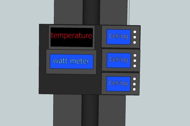
What I also wanted to do is try a surface mount version of the BMS, and we've been working on variants of this for awhile now. This is a much simpler task, using this "Lite" version. Anyway, I've been also playing around with a surface mount version of the CellLog logic that isolates and converts the CellLog's alarm outputs into LVC and HVC signals, and also the relay-based logic that will automatically turn the CellLogs on and off, if either the bike's controller is on, or if the charger is on. The idea was to do like I did before, and have the circuitry be "hidden", underneath the CellLogs. Doing this with surface mount parts freed up a lot more space than I thought it would, which then gave me the idea to also add the "Lite" balancing cell circuits. It all fit quite nicely. The resulting board would just be enough wider, horizontally, to have 8 LEDs on the right (to indicate the cells that are shunting...). I then went to work on doing a modified version of the Zephyr charge controller that I had already converted to surface mount. My original thought was that I'd just add the boards to the CellLogs, and then do the charge controller as a "lump" in the charger cable. I also thought it would be useful to have everything on one board, three 8-channel CellLogs, with the extra logic and Lite circuits, and then the charge controller at the bottom of the board. In the end, I decided to basically do the PCB in a way that would allow either option. This is what it looks like:

I had some room left over, so I also added a 4x6-to-3x8 adapter, for mapping four 6s connections into three 8s, so that three 8-channel CellLogs could be used with a 24s configuration based on using 6s packs. The LVC and HVC trip points are settable via the CellLogs. The shunt turnon point is fixed, however, at 4.15V per channel. The CellLogs stay off unless either the charger/supply is connected, and on, or if the bike's controller is on. In the case of the latter, the +5V on the throttle connector will be on. If the logic sees this is on, it turns on the CellLogs. Each board also has a set of jumper pads that can be used with a switch, if manual operation is desired.
The charge process is pretty much the same as with the full Zephyr BMS. The combination of the CellLog-generated HVC signal, and the shunt circuits will allow the low cells to catch up/balance. Whenever a shunt is active, the LED for that channel will be on. The EOC and auto-shutoff functions work the same way they do on the Zephyr board.
I'm going to submit this tomorrow, to get a small run done. We want to try building a couple, mainly to verify the layouts, etc. I may look for a couple of volunteers, with younger eyes, to help in this test phase.") I'll post something here, if that is going to happen.
I'll post something here, if that is going to happen.
More later...
-- Gary
What I also wanted to do is try a surface mount version of the BMS, and we've been working on variants of this for awhile now. This is a much simpler task, using this "Lite" version. Anyway, I've been also playing around with a surface mount version of the CellLog logic that isolates and converts the CellLog's alarm outputs into LVC and HVC signals, and also the relay-based logic that will automatically turn the CellLogs on and off, if either the bike's controller is on, or if the charger is on. The idea was to do like I did before, and have the circuitry be "hidden", underneath the CellLogs. Doing this with surface mount parts freed up a lot more space than I thought it would, which then gave me the idea to also add the "Lite" balancing cell circuits. It all fit quite nicely. The resulting board would just be enough wider, horizontally, to have 8 LEDs on the right (to indicate the cells that are shunting...). I then went to work on doing a modified version of the Zephyr charge controller that I had already converted to surface mount. My original thought was that I'd just add the boards to the CellLogs, and then do the charge controller as a "lump" in the charger cable. I also thought it would be useful to have everything on one board, three 8-channel CellLogs, with the extra logic and Lite circuits, and then the charge controller at the bottom of the board. In the end, I decided to basically do the PCB in a way that would allow either option. This is what it looks like:
I had some room left over, so I also added a 4x6-to-3x8 adapter, for mapping four 6s connections into three 8s, so that three 8-channel CellLogs could be used with a 24s configuration based on using 6s packs. The LVC and HVC trip points are settable via the CellLogs. The shunt turnon point is fixed, however, at 4.15V per channel. The CellLogs stay off unless either the charger/supply is connected, and on, or if the bike's controller is on. In the case of the latter, the +5V on the throttle connector will be on. If the logic sees this is on, it turns on the CellLogs. Each board also has a set of jumper pads that can be used with a switch, if manual operation is desired.
The charge process is pretty much the same as with the full Zephyr BMS. The combination of the CellLog-generated HVC signal, and the shunt circuits will allow the low cells to catch up/balance. Whenever a shunt is active, the LED for that channel will be on. The EOC and auto-shutoff functions work the same way they do on the Zephyr board.
I'm going to submit this tomorrow, to get a small run done. We want to try building a couple, mainly to verify the layouts, etc. I may look for a couple of volunteers, with younger eyes, to help in this test phase.
I'll post something here, if that is going to happen.More later...
-- Gary