Problems with YESA CPU-BMS

Raphael

10 W
Joined
Jan 8, 2008
Messages
99
Hi there,

this is my first post here...
We are currently building 2 recumbent bikes with Crystalite 407, 35AMP Controller, CycleAnalyst and YESA 48V 12Ah batteries.

Everything worked fine (only first test runs) until we had a problem with one of the older IC-BMS our packs were shipped with.
SAM @ Yesa recommended us to change them for newer CPU-BMS.

When we received them, we exchanged them right away on both packs. I know how to handle a soldering iron and I know some things about electronics and such, but what happens now is really not clear to me.

To say this, Sam was and is very helpfull, I'm just anxious to get the problem solved and so I'm looking for ideas here...

OK, what happens:

1. Directly on the pack, there is always good voltage (>50V), wether there is load or not.
2. Through the BMS, we have >50V without load and ONLY 1.94V with load (load means not motor running, but only connecting the controller!).
3. Connected the load for a short time directly to the batterie, everything works FINE!!! But then we would have no protection while discharging - not good.
4. Single cell voltage is fine, its always around 3.3V
5. Charger stops charging although there are only 53V (I think this is also a problem with the BMS, maybe the same)
6. Point 1-5 is the same for BOTH packs!

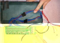
I attach a picture of our soldering / connecting work.

Thank you in advance for ANY help.
Raphael
 

Attachments

  • yesa_2a.jpg
    yesa_2a.jpg
    109.5 KB · Views: 2,034
Thanks, I was thinking the same too!
Do you see anything that could lead to a short?
 
Oh, and if it was a short, how do you "start up" the BMS from a new, so that it resets?
Sorry for my poor english skills...
 
Usually the BMS will reset as soon as you remove the load ie; disconect motor and re-connect .

If you measure the voltage, thru the bms, without it being conected to the motor, it should read 50v instead of 1.9v.. If you get 1.9v from the BMS at all times, even without it conected to anything then something is wrong with the bms or a wire is in the wrong place or something else is wrong..

There is nothing wrong with your english.. :mrgreen:
 
Ok, thanks.

But as I mentioned above, when there is no load (only my multimeter), we have >50V through the BMS (only 0.6V lower than directly on the pack, which are the losses I think and is ok).

I checked everything again right now, and I just don't get it. I can't find a short on the package, on the BMS or on the bike. Especially since we have it all 2 times, there's very little chance for doing the same mistake on both... but oh wait... it's me *jk*...
 
It's possible that the BMS trips from the surge when connecting the controller to the pack( that spark you see on the connectors ) .. try disconecting and reconecting the battery pack a few times in a row and after 2 or 3 attemps confirm if it works .. ( the capacitors in the controller should charge up and the spark won't be so pronounced )
 
that was really a good idea, thanks. But - it's not working. I do not even have those sparks. I know them from the IC-BMS (when it still worked) and from connecting directly to the pack, that works, even right now.
I really don't know what to do...
 
we just tested again, we held the multimeter to the connector, ~50V, connected it to the bike, 1.9V, released connection, ~50V, connected the bike directly to the battery (sparks appear) - and it works.
What the **** is wrong??
 
hi,

thank you for your fast answers.

hmmm...reverse polarity would mean it wouldn't work when connected to the pack directly either, right?
what do you mean by "repositioned"? yes a arranged them so there's a better fit to the pack, but no new soldering except on the + and - pole on the packs end, where i turned them 90 degrees.

please tell me when i should take better pictures when you can't see everything on the above picture!
 
negative, connected it to a 12V 20W bulp, 0V...
When connected to the bike, there are at least thos 1.9V...
 
Ooof, posting problems. Try again:

I think what Ypedal was asking earlier is if it is possible the two black multi-wire connectors somehow got exchanged? Are they keyed so it's impossible to swap them? If they got swapped, it could definitely cause a problem. It could fry the BMS board too.
 
hi,

no they are not keyed, but positive pole of the pack has to attach to c16 on the BMS which is right. we payed a lot of attention when switching from the ic-bms to the cpu-bms to keep everything ok.
no the bulp did not die, it's buring again in it's common destination. i will search for a 230v bulp (i'm from switzerland ;))

thanks to both of you.
still - the problem is not solved...
 
Raphael said:
hi,

no they are not keyed, but positive pole of the pack has to attach to c16 on the BMS which is right. the problem is not solved...

There are 2 black multi-wire connectors, with a single red lead on each. Do both red leads connect to the same positive pole on the battery pack ?

At any point during the soldering process of the new BMS, were there any accidental sparks ? :mrgreen:
 
no sparks or anything like this during soldering!
c16 goes to positive pole of the whole pack, c8 goes to cell #8, i believe. surely only c16 goes to the main positive pole.
 
oh, btw., I just saw, that when the black multiconnectors from the BMS are NOT connected to the pack, I have the sparks when connecting to the bikes, but still it does NOT power up.
 
if this doesn't work - i suggest using ggoodrem's bms setup. It is safer since it doesn't requirer fets to actually turn off the power. its also a simple clamping curcuit, and makes the controller do all the work :) - which is better in my book. Use the yesa charger + bms to recharge the battery, ggoodrem's to monitor discharge.
 
thanks for the suggestion. Where can I find info about that setup?
But hey, after all, I am not willing to pay for things that don't work. I know I have not done something wrong!

Just to say it again, clearly:

Sam is really very helpfull and gives the best to solve the problem as fast as possible. I really have to thank him for his support. I mailed him a link to this discussion a few minutes ago... maybe he will chime in.
 
As far as I know, three things can cause the BMS to trip; cell undervoltage, cell overvoltage, and overcurrent. It would be helpful to know which of these was at work here.

I would suggest measuring the voltage across each cell on the inputs on the BMS board. Hopefully there will be a spot on the board where you can place the probes. Measure between adjacent pairs of wires and move along the pack. Note the voltage reading on each cell. If one is out of whack, that could help determine the problem.

It would be good to measure both with and without a load. The load should not be enough to trip the output.
 
hi fetcher,

thanks.
i already measured voltages several times directly on the connectors to the BMS and on the BMS itself.
each cell is absolutely ok, around 3.25-3.3V.
i even measured pairs of cells to see if there's anything cabled false. it was perfect, around 6.5-6.6V the pair.

I can not measure with a load without tripping the output, I have not found such a load yet. every small load seems to trip it.

To be clear, the controller does never power up, I do not power up the motor!

It's getting frustrating at the moment... but I'll get there ;)
 
Hmm... that's tough.

You could try measuring directly across each cell and put your 12v light across the same cell as a load just to make sure there's not a cell that drops out under load.
 
Back
Top