DIY Single Cell LiFePO4 Charger

rkosiorek

100 kW
Joined
Jan 18, 2007
Messages
1,770
Location
Belleville, Ontario Canada

Single Cell LiFePO4 charger by rick_kosiorek, on Flickr

I have a few large LiFePO4 packs that have been stored for a few years without being charged. some cells are 3.3V and over. these are likely good. some cells have leaked and are obviously bad. Others read near 0V and likely cannot be recovered. a Few are over 1V but less than 2.0V so off the shelf chargers will not even start charging them. So i decided to put together a CC/CV power supply i can use to try to bring these back to life.

I have a collection of wall type power adapters from various DVD players, dead WiFi Routers etc. that i decided to re-purpose a couple of them rated 12V @ 2.0A.

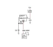
The output of the Wall adapter is fed into a 2 stage regulator. each stage has an LM338T rated for 5A. the first one is set up as a current limiter that can be switched for 100mA, 1.0A or 1.8A. this is controlled by a pair of toggle switches. both switched off the output is 100mA. either switch on adds a resistor in parallel to R3 and sets the limit to 1.0A. Throwing the other switch on as well bumps the current up to 1.8A

I figured that it would be much safer to use a low current at first for the cells under 2.0V than to try and charge them at higher currents. for flexibility i also wanted higher currents to be available.

The current limiter feeds a second LM338T used as a voltage regulator. Output voltage can be set by R9. i used a 25 turn trimmer because the adjustment can be a bit finicky. a 4A rectifier is used as a blocking diode on the output. if i forget to disconnect the charger it will not drain the battery.

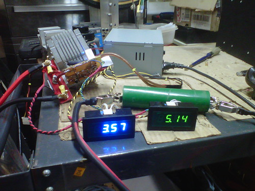
Last i wanted a voltmeter to show what was happening. the only ones i had on hand need an isolated supply. the top half of the circuit using the LM7805 and DC-DC block converter is the supply for the LED Voltmeter and can be deleted if a meter is not included.

Rick
 

Single cell charger prototype by rick_kosiorek, on Flickr

Prototype ready to go.


Single cell charger prototype in action by rick_kosiorek, on Flickr

Works okay. Load regulation is not as good as i had hoped. No load the output is just under 4V. @100mA the cutoff voltage is 3.65V. @1.8A it is down to 3.45V. But since it never exceeds 3.65V when connected to a battery i feel safe to use it. I do not intend for this to fully charge the cell. I just want the voltage up high enough so i can charge and balance it together with the rest of the pack.

rick
 

5A-LiFePO4 cell charger-V2_1 by rick_kosiorek, on Flickr
I decided to try a 5A version of the single cell charger using LM338 linear regulators. I used an old ATX computer power supply that i modified to work as a bench top supply. it can source up to 20A on the 12V line so it is ideal. it was rescued from an old dead desktop computer that would otherwise been thrown away.


5A LiFePO4 Charger by rick_kosiorek, on Flickr
I built the circuit on a chunk of perf board. I thought i could get away with a chunk of aluminum as a heatsink, but at 5A it got way to hot. So i bolted the bar to the CPU Cooler and fan i also removed from the same junk computer.


5A LiFePO4 Charger-2 by rick_kosiorek, on Flickr
this photo shows the unit charging a 10Ah LiFePO4 cell. it is almost at end of charge.

the circuit is built using one LM338 as a 5A current limited source. the second LM338 is set up as a 3.65V regulator. i originally used 14AWG wire from the charger to the cell. this proved inadequate. at 5A there was almost 0.2V drop in the cable itself. I upgraded the wire to 8AWG to limit the drop.

theoretically the circuit should supply 5A until the output reaches 3.65V and then the voltage should hold steady at 3.65V with the current tapering off until end of charge.
It does not work this way in practice. the Current limiter limits the current to 5A. the voltage regulator acts as a simple pass element until the voltage rises high enough for it to start regulating. that happens at about 3.45V. At 3.45V the Voltage regulator starts regulating and using power itself. as it starts regulating it uses more and more power internally reducing the amount of power available for charging. this results in a less than ideal but still safe charging curve of 5A CC until the cell hits 3.45V and than the Voltage slowly rises as the current reduces until the cell hits 3.65V @ 100mA charge current.

Full Charge takes about 5Hours. the time could be cut by an hour or so if the charger maintained the 5A to 3.65V and then only tapered the current. this is impossible with this ultra simple circuit.

I still need to do a whole bunch of cells. And every once in a while i need to charge a single cell. so I'm thinking of building a larger version that will be able to do 10A using a LM317 and a couple of MJE2955 transistors as a constant current source. That will work for the CC part. I'm thinking i do not want put the regulators in series, but in parallel. the CC source will work up to 3.65V, switch off and then a 3.65V CV source will switch on. I'm still working on a schematic. so far my attempts look far too complicated. so i'll keep using this circuit until that happens.

rick
 
Cool that you have the skills, must be very fun to be able to do stuff like that.

But the rest of us more moronic types are better off to get ahold of an RC hobby lipo charger, and set it to 1s lifepo4. Fool proof method for us fools.
 
One day I noticed that some PC PSU have a 3V3sense line and did a simple experiment to see what range of output voltage I could get from the 3V3 rail by fiddling with the sense line. On the PSU I tried it could go up to some 3.8V unloaded if I recall, which is perfectly enough to charge a single LiFePO4 cell (to charge upto 3.65V). I got the feeling though, that the current is lacking too much on the top of the voltage range and need to make more detailed tests to check this, when I have the time. But if this works it's a perfect solution, since those rails are supposed to source a bunch of Amps. A low-power circuit with 2 ampops (and there's 12V available to power them :)) could control the sense line in order to control voltage and limit current. I have a control circuit designed (partly tested), I'll try to put here later.
 
Been working on this myself, for topping and balance. The circuit is dead simple and works well. It uses a shunted 12v supply feed through a lm317 regulator, the difference is R2 is replaced with a 3.6 zener diode, it delivers full amps than goes CV when zener conducts and holds 3.65 volts forever. I have yet to figure out how to end charge at 100 to 200 ma. , Any ideas, sure are welcome !

The end plan is a circuit for each cell in pack, all driven by a high frequency inverter, coupled with a cap and bridge circuit, for isolation.
The regulator circuit delivers 1.5 amps with out a sweet, which is fine for a healthy pack. after a bulk charge.

Edited due to retard spelling, pardon me.

Thanks to all .
 

Attachments

  • E.S. share.jpg
    E.S. share.jpg
    5.6 KB · Views: 6,826
i also have an RC charger. actually i just bought it. what i like about this circuit is that i can just hook it up and plug it in. i don't have to do the 50 question through 60 menus before i start to charge.

i also did another circuit using a TL431 shunt type regulator to provide the reference voltage. i had to use the 1.24V version and instead of the LM338 i used an LT1084 (pin compatible) LDO regulator. the LT1084 is also cheaper at less than 2 bucks.

the circuit worked much more precisely. the regulation through the TL431 is very precise.


5A cc-cv-0V9 by rick_kosiorek, on Flickr

rick
 
Can't read schematic, even after download and zoom. i am interested Thanks for sharing

Pete
 
torqueon said:
Can't read schematic, even after download and zoom. i am interested Thanks for sharing

Pete

just click on the image twice. after the second click in the upper right of the screen click "View All Sizes". you can then download a larger picture.

but i have also uploaded a pdf.

rick
 

Attachments

  • 5A cc-cv-0V9.pdf
    13.7 KB · Views: 315
Yeah, one nice thing about my stupid purchase of an Imax b6 charger, is I leave it set for lipo charge 1s now. Things about useless except as a 2 amp 1s charger. So it's never changed from charge 1s setting. :lol:
 
I have to admit that I should of invested in these balance chargers, that folks use here. My D I Y nature and interest in electronics get me in trouble at times
But than again its a fun hobby with propose!
 
The saga continues...

My packs are too large for any of the balance chargers out there. but i occasionally let the packs sit too long between charges and some cells self discharge more quickly than others. at that time it is convenient to charge individual low cells to bring them more into line and reduce the workload of the BMS which does the balancing. that is why i started on the individual cell charger.

I am still capable of making mistakes though. i made one making the 5A version of the charger. I used a heatsink that was almost but not quite adequate. It would run at the 5A level for a couple of hours, enough to get the cell up to around 3.5V or so and then the regulator would start to heat up. the internal thermal shutdown would start kicking in and fold back the current limit to a lower level to prevent a meltdown. So I changed the Heatsink to a more effective one. now i can charge at 5.1A until the cell hits 3.65V.

Well almost. the 0.25R 10W resistor that sets the current also heats up and changes it's value as it does. but this is a small effect. the current slowly drops down to 4.8A until the 3.65V trip. charging an empty cell takes around 3.5hrs.


5A cc-cv-1v0 by rick_kosiorek, on Flickr


5A cc-cv-1v0-1 by rick_kosiorek, on Flickr


5A cc-cv-1v0-2 by rick_kosiorek, on Flickr

I also made a change in the schematic. I don't wan the charger to drain the cell if I leave the charger connected to the cell with the power off. D2 prevents the cell from discharging through the regulator and power supply. but since the voltage drop of D2 changes depending on the current, i wanted the voltage sense to be after the diode for better accuracy. that means that there would always be 20 to 40K across the battery. so i added Q1. as long as there is 12V at the input of the regulator, R7 will turn on Q1 and turn on the feed back path. that leaves only the meter which is a 2M or so to drain the battery. that i can live with.

rick
 
Excluding the meters, the total cost of parts for the 5A charger is less than $15.00. I mean you have to recycle a power supply and a heatsink. i think that is quite reasonable for what it is.

Unfortunately I suffer from what my friends call "Tool Time'Itis". Remember the old Tim Allen TV show "Tool Time" and the main character "More Power" Tim Taylor? Frankly IMHO he is an underachiever.

while working out the bugs for the 5A version I realised that I could add a couple of resistors and power transistors and up the current to 10A. Here is the schematic.

10A cc-cv-1v0 by rick_kosiorek, on Flickr

now i have to go dig out those MJE2955's i know i've got somewhere in the bins

rick
 

Attachments

  • 10A cc-cv-1v0.pdf
    17.6 KB · Views: 250
  • 5A cc-cv-1v0.pdf
    14.3 KB · Views: 200
I invested in one of those Hyperion EOS 1420i RC chargers. it is nice because it can handle up to 14 cells in series. my packs are 48S. so i was able to split the pack into 4 and charge it as 4 separate strings of 12 cells. each string was balanced within a few mV.

but i was not able to do this without problem. in storage some of the cells had dropped to 2.0V. the RC charger will not charge cells that are this low. even as a 1s charger, it would not charge these cells for longer than 5min at a shot. restarting the charge repeatedly until the cell voltage rose to over 2.7V until it would charge the cell normally.

so there still is a use for a single cell charger. that would be to precondition deeply discharged cells and bring them up to a level that is acceptable to the balancing charger. tha will be useful when i start sorting through the power tool packs that i have to grade the cells. so i have decided to keep 2 of the lower current designs. a 1A version to condition the cells that are under 2.0V and a 5A version for the cells that are just over 2.0V

the 10A version works very well. needs a big heatsink and is at least for me unnecessary now that i have the RC charger. and for the life of me i can't figure out why i stubbornly refused to buy an RC charger until now. it still can't charge my packs directly. but it sure simplifies and speeds up getting the packs ready for use after months of storage.

rick
 
It's over a year since anyone commented on this charger but the following point may be worthwhile.

LiFEPO4 cells do not tolerate being floated at maximum charging voltage for long periods. If a charger "floats" cells and they are left in the charger in this mode for long periods it will substantially reduce their cycle lifetimes.

Chargers with a reducing current "tail" that fully remove voltage when current falls to say 10% of I_max do not have this problem.
 
Russell McMahon said:
It's over a year since anyone commented on this charger but the following point may be worthwhile.

LiFEPO4 cells do not tolerate being floated at maximum charging voltage for long periods. If a charger "floats" cells and they are left in the charger in this mode for long periods it will substantially reduce their cycle lifetimes.

Chargers with a reducing current "tail" that fully remove voltage when current falls to say 10% of I_max do not have this problem.

you are very correct. but i never intended these to be used completely stand alone, unattended chargers. my purpose was to be able to quickly charge up individual cells. mostly to bring up cells to a known state of charge before assembling into packs.

rick
 
Back
Top