
wojtek
100 kW
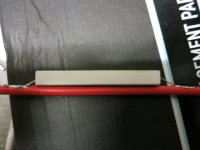
following ES members' advice, i have installed a resistor on my battery pack:
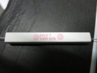
17w / 100 Ω / 10% tolerance
https://www.electronic-shop.lu/passive-bauelemente/widerstande/draht-hochlast-vitrohm/kh-serie-10-17-w/110463.html
When connecting the battery to controller, i am getting only a weak spark. But there is still a spark. I wonder if i could get another resistor that could completely eliminate the spark? what would the spec be?
And what is the relation between those the spec [17w / 100 Ω / 10% tolerance] and eliminating the spark. Which spec plays the role to kill the spark? [all?]
I also got wirewound resistor , 50 Watt at 25°C *, aluminium housed, fully insulated, 1% tolerance, 100 Ω..
https://www.electronic-shop.lu/passive-bauelemente/widerstande/draht-mil-standard-vishay/rh-serie-1-50-w/107166.html
just found this one with lower 0.5W but higher 470 Ω.... would that be better?
https://www.electronic-shop.lu/passive-bauelemente/widerstande/metallschicht-yageo/mf0204-serie-1/102293.html
thanks!

") it all makes perfect sense now
it all makes perfect sense now