EMC-1000 900w Charger FAQ Info from BMS Battery

deVries

100 kW
Joined
Jul 10, 2008
Messages
1,545
Location
Solar Powered 3000w Texas
Methods thinks this is a good/decent charger, except for the high shipping costs, so I thought this thread should contain all the info we can find on this charger & put it in one place, here. Current price is $88 usd +expensive shipping July 2012. I bought one to try so will report to this thread over time how well it works for me. [Edit: I should add that there are higher quality & more efficient Power Supplies that can be easily converted *with* some DIY skills, and one excellent option is the Meanwell RSP-1000 though the voltage is limited to 55v. Also, Alan B. is going to be converting a *very* efficient PS to a charger too up to 58v 6A.]

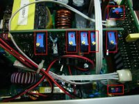
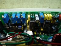
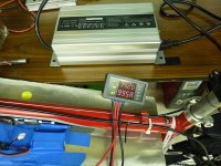
If you buy one of these EMC-1000 chargers, then I highly advise you do a "burn-in" of 5-10 charge cycles upon receipt. Most failures happen within the first 5-20 charge cycles, so you want to be able to replace a defective unit upfront w/warranty replacement.

Methods comments:


methods said:
I set up a spreadsheet comparing nearly every aspect of the various models. After focusing down on the 1.2KW and 900W I found that the 900W was a "better value" in nearly every important category

$ / Watt
Watt / kg
Watt / Volume
% actual output vs rated output

This boils down to the fact that the 900W is "maxing out" its housing while the 1.2kw is under powered for its housing. This large 1.2kw housing takes it out of the running for being "portable".

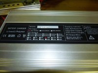
My impression of the 900W units upon arrival was that they were very much within the realm of "backpackable". They are small and tidy. The voltage and current markings are accurate enough for indication use. The power cord that was supplied was beefy 14G.

They tuned the supply to the 75.6V @ 10A that we requested and even supplied mating Anderson connectors (though they were counterfeit)

We steered away from the 1200W unit because of a few factors

Twice as heavy
Twice as big
Half again more expensive
Power increase was not worth these costs

So in the end we felt that ordering a supply that could fit in a backpack, was light weight, cost effective, and could put out an honest 750W was the best for us and our customers.

Anyhow - this was a surprise for us as my gut feeling was that we should get the 1.2KW unit. It is always wise to do a proper cost-benefit analysis because sometimes the results will surprise you. This of course depends on what you value though - and we value portability. If on the other hand what you value is something that is overbuilt - the 1.2KW unit would have won out.

-methods
 
Maybe Rolf or certainly Methods or Matthew knows the following & can share their knowledge... :D

rolf_w said:
Could someone map the trim-pots functions to the locations in the following picture?

The EMC-1000 uses a separate PCB for the logic circuitry and places the trimpots at the top (very handy). The labels/numbering on the PCB seem to be the same though and read (comments copied from Doc):

1 = W503 ; turn CW to increase V_out ; range 57V - 116.5V if W4011 set to max V_out
1a = W502 ; is for ??? (not mounted)
2 = W501 ; is for LED lamp indicator adjustment
3 = ?W401? ; is for current adjustment (can't see the label)
4 = W402 ; is also for current adjustment ( probably the fine or coarse)
5 = W4011 ; turn CCW to increase V_out ; shifts the range of W503, kind of offset?; I tried W503 ranges for a number of fixed W4011 positions e.g. 47.0-105.7V, 42.5 - 96.0, 32.5 - 73.5, 28.0 -63.5; I was able to trim down V_out minimum to 2V!
6 = ?
7 = ?

rolf
 

Attachments

  • trimpots_emc900&notes.jpg
    trimpots_emc900&notes.jpg
    95.1 KB · Views: 7,680
This unit is more than a year old, so not certain of any design or layout changes. Here's where captain387 adjusted his voltage & current settings on his EMC-1000 900w charger...

captain387 said:
Well, the charger was second hand and the previous owner had it set at 72v, 11 amps, I think.
Everything with my bike I have set it to be extremely conservative from charging at below 1 c and running my speed control at 60% its rating.
I do plan on enlarging my battery pack in the future and wanted to get a charger that could meet those needs.

Here is the inside of my charger and the adjustment pots I used.

 
Alan B said:
They (evassemble) indicated the shipping fees were calculated for batteries (early in the BMSBattery charger problem thread) and that you can request a specific shipping quote. Has anyone had success doing this? That would make these chargers a lot more interesting (if the shipping were reasonable)!
EVassemble sells a $140 more efficient 900w charger that may have cheaper shipping too. The BMS Battery people didn't offer any cheaper way, though sea/surface is cheaper. They just don't want the hassle doing that unless you buy 500. :lol:
 
FYI: BMS Battery no longer produces the 900W charger that I reviewed. It had a display on the front and was in the silver housing. Now they sell one for the same price but with no display in a black housing.

Just mark the knobs and then turn them. What changes?

There is almost always a clue on the silk screen of the PCB as to what the pot does.
I
V
etc

-methods
 
I have recently (Sept. 2012) bought the EMC-1000, 900 W Battery Charger from BMS Battery. As I am from Germany, I had it configured to 230V.
Problem now is that in about 80% of the sockets I plug it in, the fuse blows (Household fuses here are 16A fuses). It must be the switch-on current that causes the problem. A friend told me, that there are some high-capacitance capacitators installed that produce a short at switch-on and that a small resistor could help.

Has anyone had the same problem and solved it? I don't know where to put the resistor in the circuitry of the charger.

I use this charger for a 36V/22,5 Ah LiCoMn Battery and adjusted it to 41.5V. Max. current is 18A. It is very nice when I travel long distances with my velomobile and can charge the battery within approx. 1,5h. But I have to ask people in shops and homes if I could use their sockets. You can imagine that I don't want their fuses to blow after they have agreed to give me some electricity.
 
If the fuse blows during charging then all you need to do is turn down the charge current - blue 10 turn pot

If the fuse blows right at the moment you plug it in... yea... it is the input capacitance. Here is a ghetto way to do it:

and I mean GHETTO... but this illustrates the point

Find an old extension cord
cut one wire
solder in a large resistor. Large as in physically large... so 5W or 10W or 20W. The resistance is not all that important - anything from a few hundred ohms to a few thousand ohms will do it.

So you solder this resistor inline with your extension cord.
Now we call this your "precharge cable"

You turn the charger OFF (this is important!)
Plug your charger into the precharge cable
plug your precharge cable into the wall
wait a while... maybe a few seconds maybe a minute (depends on resistor value used)
The resistor will get warm

What is happening is that we are slowly charging up that capacitor bank on the input of the charger

Now... NEVER TURN IT ON WITH YOUR PRECHARGE CABLE INLINE
This will result in the precharge resistor burning up - for sure - bad news

You want to remove your precharge cable
plug the charger into the wall

Now you can turn it on and it will work
Just keep it plugged into the wall and you will be fine
If you ever unplug it from the wall you can repeat the procedure

So yea
Your fuses blew because the inrush current of the capacitor bank was too high. A current limiting resistor corrects this... but you cant solder in that resistor permanent because it would limit the current needed during operation.

IF there is no bleed down resistor in the circuit then if you always turn off your charger before unplugging it **it should** maintain its charge
I bet there is a bleed down resistor tho...

I would cut the bleed down resistor out of the circuit
It is only there to make the charger safe to work on... i.e. so that it will not store high voltage.

Start a fire!
Good luck

-methods
 
Friendly Fire said:
I have recently (Sept. 2012) bought the EMC-1000, 900 W Battery Charger from BMS Battery. As I am from Germany, I had it configured to 230V.
Problem now is that in about 80% of the sockets I plug it in, the fuse blows (Household fuses here are 16A fuses). It must be the switch-on current that causes the problem. A friend told me, that there are some high-capacitance capacitators installed that produce a short at switch-on and that a small resistor could help.

Has anyone had the same problem and solved it? I don't know where to put the resistor in the circuitry of the charger.

I use this charger for a 36V/22,5 Ah LiCoMn Battery and adjusted it to 41.5V. Max. current is 18A. It is very nice when I travel long distances with my velomobile and can charge the battery within approx. 1,5h. But I have to ask people in shops and homes if I could use their sockets. You can imagine that I don't want their fuses to blow after they have agreed to give me some electricity.

do you plug the battery into the charger first and then plug the charger into the wall outlet?

have you investigated to see if there is a switch inside to set the line voltage and the switch is set to 120V?
 
I tried to measure the output voltage of my charger but nothing is displayed. Is there a way to activate the charger without pluggin it into a battery?

Thanks
 
I recently ordered and received a 900W charger from E-Shine Electronics which seems to be similar to the one from BMS Battery. It's set at 75.6V, 10A. It has the same adjustment pots (W503, W502(not installed), W501, W401, W402, and W4011) as some of the other chargers but I have not tried adjusting any yet. I am waiting to hear from the supplier with some instructions to see if they jibe with the description given earlier in this post. I have only completed one charge cycle and noticed that the green charge complete LED comes on at about .05C yet the charger continues to output about half and amp as opposed to disconnecting the output relay and totally terminating the charge. I plan to make some mods once I get it all figured out. Here are some photos:
 

Attachments

  • P1080414.JPG
    P1080414.JPG
    93.7 KB · Views: 7,277
  • P1080415.JPG
    P1080415.JPG
    99.8 KB · Views: 7,277
  • P1080422.JPG
    P1080422.JPG
    93.2 KB · Views: 7,276
  • P1080424.JPG
    P1080424.JPG
    95.6 KB · Views: 7,277
  • P1080428.JPG
    P1080428.JPG
    71.5 KB · Views: 7,277
My fantasy is to find one of these charger manufacturers who will ship in bulk for cheap... then I want to install a Stand Alone CA into the unit for ultra accurate Voltage, Current, Ah, etc data. It would be a bit of a splurge - but cool. Maybe make the CA detachable so that it can also be used as a lab test device.

Dude - if someone can do the footwork to find a reasonably priced charger I will convince Matt to reach into his tight ass pocket and buy a batch... then he and I can geek on them to... er... make them better :D

I want a charger that can run from 50.4V to 100.8V
10A minimum with 20A being the dream

I say we go more expensive... solid state... small enough and light enough to go in a packpack...
These chargers are cool and all - but inside is a huge fragile transformer :?

Man - there has got to be an application out there that will serve as a good donor supply.

-methods
 
jabbor wavber so can we get a number and go forward. 84v-36v - 20 to 10amp. dials for voltage and amps and led's. That's it. Let's keep it simply. And i what. shuck up.
 
methods said:
If the fuse blows during charging then all you need to do is turn down the charge current - blue 10 turn pot

If the fuse blows right at the moment you plug it in... yea... it is the input capacitance. Here is a ghetto way to do it:

and I mean GHETTO... but this illustrates the point

Find an old extension cord
cut one wire
solder in a large resistor. Large as in physically large... so 5W or 10W or 20W. The resistance is not all that important - anything from a few hundred ohms to a few thousand ohms will do it.

So you solder this resistor inline with your extension cord.
Now we call this your "precharge cable"

You turn the charger OFF (this is important!)
Plug your charger into the precharge cable
plug your precharge cable into the wall
wait a while... maybe a few seconds maybe a minute (depends on resistor value used)
The resistor will get warm

What is happening is that we are slowly charging up that capacitor bank on the input of the charger

Now... NEVER TURN IT ON WITH YOUR PRECHARGE CABLE INLINE
This will result in the precharge resistor burning up - for sure - bad news

You want to remove your precharge cable
plug the charger into the wall

Now you can turn it on and it will work
Just keep it plugged into the wall and you will be fine
If you ever unplug it from the wall you can repeat the procedure

So yea
Your fuses blew because the inrush current of the capacitor bank was too high. A current limiting resistor corrects this... but you cant solder in that resistor permanent because it would limit the current needed during operation.

IF there is no bleed down resistor in the circuit then if you always turn off your charger before unplugging it **it should** maintain its charge
I bet there is a bleed down resistor tho...

I would cut the bleed down resistor out of the circuit
It is only there to make the charger safe to work on... i.e. so that it will not store high voltage.

Start a fire!
Good luck

-methods


Helo methods,
thanks for the reply. I get your idea. But the charger has no on/off switch. You turn it on by pluging the cable into the wall. And the fuse blows, no matter if there is a battery on the output or not. But if I turn the fuse back on shortly after it blew (and the charger is still pluged into the wall), the charger works. Same if I unplug it and replug it within maybe ~10 seconds. I think this is evidence enough that the inrush current from the 2 250V/1800µF caps cause the problem (can be seen on the pictures, only in the pictures, they are 200V/1000µF). As soon as they are charged, the fuse blows no more.

Even if there was an on/off switch, it would have to be installed after the caps, so they are being charged by your precharge cable, right?
I don't like this ghetto solution very much. I think I will try a combination of a resistor and a relais parallel to the resistor that will shunt the resistor after some milliseconds.
 
methods said:
I say we go more expensive... solid state... small enough and light enough to go in a packpack...
These chargers are cool and all - but inside is a huge fragile transformer :?

Couldn't you somehow glue the transformer to protect it from vibration so you can carry it with you? The charger is quite big but maybe it could still be carried around if protected correctly?
 
actually, from what i have seen in looking inside these BMS battery chargers, the fragile part is where the output choke is soldered onto the traces on the pcb. the choke is big and tall and heavy, and the traces are flat and the soldering job done when the girls solder the choke to the pcb is usually totally inadequate to even carry the current, much less be able to physically 'lock' the choke to the pcb by filling the through holes with solder, which they never ever do. it is a wham bam thank you mam sorta soldering. i am sure they have piles of charger pcb's they have to go through to make their work quota so you can understand why it is that way. but i think that is the bigger risk of failure than the transformer which is usually soldered during reflow and the solder joints are always sound and strong.

all jmho.
 
Hi,
I just got my EMC 1000 charger and I'm not sure of the polarity of the leads. First, they didn't send it with the 5.5mm bullets I requested, and I can fix that quick and easy. The problem is there is a blue wire and a brown. I plugged the charger in and put my meter on it and see about 5v with the positive probe of the meter to the blue and -5v with the negative to the blue so I assume the blue is the positive side of the charger? I want to be 100% certain to avoid damaging my pack, or the charger.

I want to replace the bullets so I can check the voltage since it's marked 72v 10A and I requested 82v which would give me 4.1v per cell for a 20s pack. I charge to 4.15v with the balance charger but wanted to leave a little extra room when bulk charging.

So, any tips on the polarity thing?

Edit- I pulled the cover and the silk screen shows the brown wire being the positive, but I've checked 4 times now with the meter and I see 4 to 6v testing the blue as positive and -4 to -6v testing with the brown as positive so I don't know whats going on. I read there is a sensor or some sort that won't turn the charger "on" and supply voltage without the pack plugged in, so that might explain what seems to be a contradiction. I'm still at a loss and won't use my new charger till I know for certain though.
 
there is a relay on the output so until you plug the battery into the charger it will not push current.

the brown wire is positive and the blue wire is negative. i think that was already covered earlier in this thread if you read it.

it will not charge your battery if you plug the battery in reversed. but at least it will not blow anything up.
 
dnmun said:
there is a relay on the output so until you plug the battery into the charger it will not push current.

the brown wire is positive and the blue wire is negative. i think that was already covered earlier in this thread if you read it.

it will not charge your battery if you plug the battery in reversed. but at least it will not blow anything up.

Thanks for the verification. It very well may have been covered, and I read through a few threads about these chargers but I may have missed it.

As I expected, the charger isn't putting out the 82v I had specified when ordering since it's marked 72v/10A and I see 75.4v, and I can look through the threads to find the pot for the voltage, but I'll need to adjust it up where I want it while it's charging right?
 
the 75.4V may be what your pack is at now and it will charge up further if you leave it on the charger. keep track of the individual cell voltages so that the BMS doesn't shut off at the 3.9V HVC and when it gets to the top of what it will push the voltage up to without the BMS shutting off, then you can adjust it up again and wait for the pack to charge up more and keep doing that until it gets to the final voltage you want.
 
EMC-1000 900w Charger: household fuse blows

Postby Friendly Fire » Sun Nov 11, 2012 11:36 am
I have recently (Sept. 2012) bought the EMC-1000, 900 W Battery Charger from BMS Battery. As I am from Germany, I had it configured to 230V.
Problem now is that in about 80% of the sockets I plug it in, the fuse blows (Household fuses here are 16A fuses). It must be the switch-on current that causes the problem. A friend told me, that there are some high-capacitance capacitators installed that produce a short at switch-on and that a small resistor could help.

Has anyone had the same problem and solved it? I don't know where to put the resistor in the circuitry of the charger.

I use this charger for a 36V/22,5 Ah LiCoMn Battery and adjusted it to 41.5V. Max. current is 18A. It is very nice when I travel long distances with my velomobile and can charge the battery within approx. 1,5h. But I have to ask people in shops and homes if I could use their sockets. You can imagine that I don't want their fuses to blow after they have agreed to give me some electricity.


I have this charger (50 volt version) and I found plugging it in to 120VAC would cause an arc at the AC plug and make the lights in the room flicker though I did not trip a breaker. I removed the cover and found that the input circuit has no inrush limiter. :( There appears to be a spot for one labeled K401 which is jumpered. I added two series inrush limiters that I had handy which are rated at 1 ohm, 16 amps each so 2 ohms total. This helped reduce the arc significantly but this value is not optimum so I have ordered a 5 ohm 20 amp unit that should solve the problem. This could also be placed in series with the AC socket where there is more room to mount it. The 5 ohm unit + input circuit resistances should limit the momentary inrush to less than 20 amps which should solve the problem. The 5 ohm inrush limiter unit is an AMETHERM Part # SL32 5R020 about $2.70

Other than the surge issue I tested the unit at 16 Amps out (50V) and found it was stable and ran very cool. Probing with an IR thermometer found no issues at all even with the covers off hence reduced heat sink area and poor fan air flow. The soldering was quite good. I have added external pots to allow control of voltage and current.
 
i have a buncha 5ohm 6.3A ICLs that i sell too. i think that would handle the 900W charger too. the Vpower chargers would all blow out their thermistor so they needed replacement on about 60% of the chargers.
 
I need to update my EMC-1000 to 59.5V, how do I do to see the charging voltage and update the voltage?
2013-08-05%2019.15.46.jpg


Thanks
 
Back
Top