
Yo guise
im reading the forums since 3 month but didnt register yet so dont worry")
im currently developing a cheap and lightweight bms that can be used in combination with HK Lipos and i want to hear your oppinion about it
reasons for me to develope a new bms are that bms systems currently on the market are either too big, too expensive, not expandable or just not programmable
this is a approach to maybe develope a community bms that can be adjusted to everyones needs
Features:
- capacitive + resistive balancing
- buzzer to notice user
- temperature sensor
- 2 Leds (not yet sure what they will show)
- communication between battery packs
- extendable up to ... 10000S in series
Electrical Specs:
- standby current of about 100uA (which is about 7 years on 5000mAh)
- balancing current 1-30mA (depends on voltage difference of cells)
Physical Specs:
- small dimensions: 40x25x8 mm
- 2 connectors for 6s lipos (6s2p made easy)
Functional description:
Balancing:
- bms should be left connected all the time
- if charging is detected and cell voltage > 3.8? balancing starts
- voltages are sent to other bms boards periodically
- all boards target the same voltage on every cell
- balancing ends when all cells are balanced or battery is used
LVC:
- while battery is used bms stays active and monitors all cells individually
- if LVC condition is detected (one cell below 3.0V?) bms starts buzzing
- it is not planned to cut the battery
HVC
- currently not really planned ... maybe add one connection to notice external charger to stop charging?
- starts buzzing
Temperature
- start buzzing if battery gets hotter than 50°C?
Hardware:
- the bms is based on capitative balancing, so no energy gets wasted! (but there is also a resistor as alternative)
- i use 2 analog switches to switch a capacitor from cell to cell and sometimes to the adc to balance and measure
- the boards are connected via optocoupled uart
the balancing idea is based on a schematic i found on a german electronic forum:
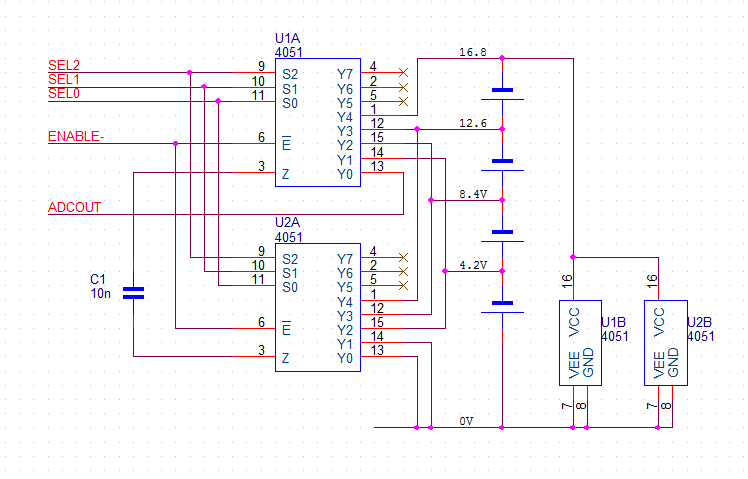
its simple and does not need much parts -> cheap
Expected price per 6s Battery:
- parts: ~10$
- pcb: ~5$
means: price for 18sXp = 45$
i guess i will order the first prototype pcbs in 1-2 weeks
there are still some pins unconnected of the Atmega88 so im glad to hear your improvements :lol:
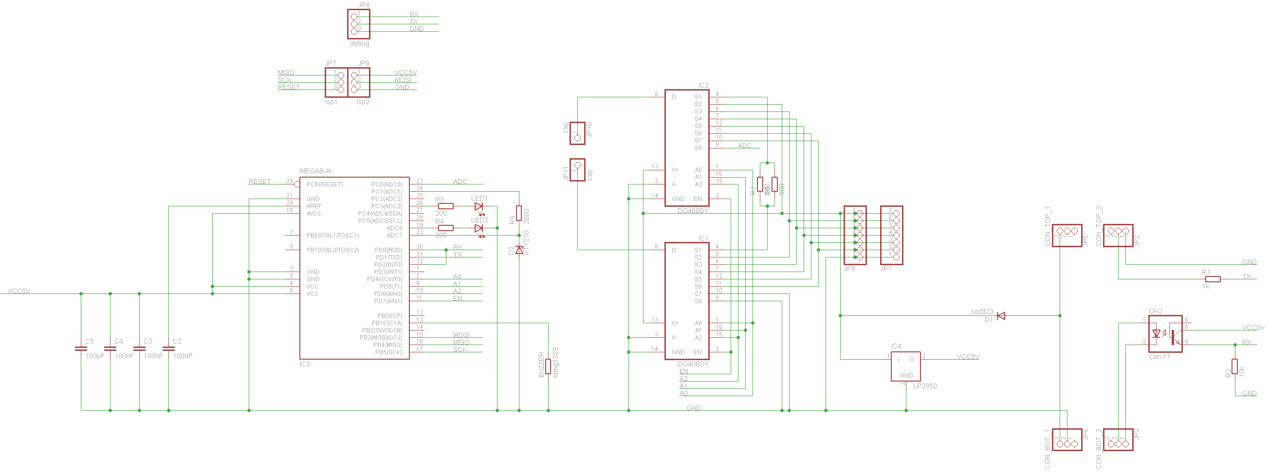
JP10+JP11 = Supercap 0.1mF (not uF!)


im reading the forums since 3 month but didnt register yet so dont worry
im currently developing a cheap and lightweight bms that can be used in combination with HK Lipos and i want to hear your oppinion about it
reasons for me to develope a new bms are that bms systems currently on the market are either too big, too expensive, not expandable or just not programmable
this is a approach to maybe develope a community bms that can be adjusted to everyones needs
Features:
- capacitive + resistive balancing
- buzzer to notice user
- temperature sensor
- 2 Leds (not yet sure what they will show)
- communication between battery packs
- extendable up to ... 10000S in series
Electrical Specs:
- standby current of about 100uA (which is about 7 years on 5000mAh)
- balancing current 1-30mA (depends on voltage difference of cells)
Physical Specs:
- small dimensions: 40x25x8 mm
- 2 connectors for 6s lipos (6s2p made easy)
Functional description:
Balancing:
- bms should be left connected all the time
- if charging is detected and cell voltage > 3.8? balancing starts
- voltages are sent to other bms boards periodically
- all boards target the same voltage on every cell
- balancing ends when all cells are balanced or battery is used
LVC:
- while battery is used bms stays active and monitors all cells individually
- if LVC condition is detected (one cell below 3.0V?) bms starts buzzing
- it is not planned to cut the battery
HVC
- currently not really planned ... maybe add one connection to notice external charger to stop charging?
- starts buzzing
Temperature
- start buzzing if battery gets hotter than 50°C?
Hardware:
- the bms is based on capitative balancing, so no energy gets wasted! (but there is also a resistor as alternative)
- i use 2 analog switches to switch a capacitor from cell to cell and sometimes to the adc to balance and measure
- the boards are connected via optocoupled uart
the balancing idea is based on a schematic i found on a german electronic forum:
its simple and does not need much parts -> cheap
Expected price per 6s Battery:
- parts: ~10$
- pcb: ~5$
means: price for 18sXp = 45$
i guess i will order the first prototype pcbs in 1-2 weeks
there are still some pins unconnected of the Atmega88 so im glad to hear your improvements :lol:
JP10+JP11 = Supercap 0.1mF (not uF!)
