Current Limiter design for HP server PS - DPS-600PB

heathyoung

100 kW
Joined
May 27, 2009
Messages
1,545
Location
Newcastle, Australia
TL:DR - circuit allows high current server power supplies to be used directly as bulk chargers, by adjusting their output voltages all together to current limit. Allows multi-kw charging really, really cheaply.

OK - I have a large collection of HP power supplies, removed from decomissioned servers from work.

While they work great for powering LiPo chargers, they really aren't suitable for bulk chargers - put them on too big a pack and they just shut down. Sigh.

I considered making big, expensive, high-current buck converters, but the thought of designing a 50A buck didn't really appeal - big bulky, and expensive. :?

While messing with a HP DPS-600PB, I discovered that it has an adjustment range of 8-13.5V reliably. Great, but what's the use of only having one adjustable? People have been having issues with killing meanwells because they only adjust one while bulk charging. 8-13.5V is a great range when charging 3S, but I want to charge more than 3S.

So what to do? Adjust all of them together, from one point. How? Isolate them. How? Optos.

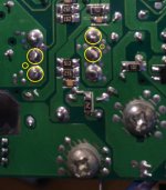
HP DPS-600's have a voltage adjustment pin - Pin 9.

Here is a pinout swiped from an RC site

PIN ------------ Ribbon Wire
1----------------- +5VSB, not on ribbon wire
2----------------- +5VSB, not on ribbon wire
3----------------- +5VSB, not on ribbon wire
4----------------- 3 (Controls fan speed)
5----------------- -12V, not on ribbon wire
6----------------- 5 (PsKill)
7----------------- 6 (not sure what this one does)
8----------------- Ground, not on ribbon wire
9----------------- 8 (Voltage Adjust)
10---------------- 4 (PsOn)
11---------------- 9 (Current Share)
12---------------- 7 (not sure what this one does)

Shorting 6-8-10 turns the PS ON.

Shorting 4-8 slows fan speed to minimum.

Putting a variable resistor between 3-9 allows voltage adjustment up to 13.8V (5V)
Putting variable resistor between 5-9 allows voltage adjustment down to 8V (-12V) - OCP is 30A at 8V though.

Now, the juicy stuff - Circuit Notes

There are two elements to this circuit.

Voltage Control (more on this later) and current control. Current control is achieved through the use of a LM358 as a comparator, powered
through a low dropout 5V regulator running on the '12V rail' (which is adjustable between 8-13.5, and is the reference voltage for the comparator).

When the current limit is exceeded, the output of the comparator (pin 1) goes high, and the optocoupler starts to conduct, pulling the voltage control pin (pin 9 on the PSU) down using the -12V rail (pin 5 on the psu). This causes the power supply to reduce in voltage so that the current limit is not exceeded.

The second opamp is simply a voltage follower, and causes the second optocoupler to do exactly the same thing.

One opamp is capable of driving 40mA, each optocupler consumes 15mA - so the two opamps can drive 4 optocuplers between them - enough for 4 power supples, or if the current is dropped to the optocoupler LED's by increasing their series resistors, they could drive 6.

The voltage control works by using a TL431A precision zener, when the voltage reaches its set point, it forces another optocoupler to pull the shunt reference resistor to ground, forcing the comparator to go high, and switch on the optos and pull down the voltage on all of the supples. The 'BMS' point serves exactly the same purpose, and does exactly the same thing when it is pulled low by an optocoupler transistor.

The voltage control section is neccesary only if the voltage of the power supply is too high for your application. But is probably a good idea in case something happens and a PS drifts high.

The component values shown at the moment are experimental ONLY - this design will be revised as it is being tested and built.

There are a few component values that will require changing - the shunt resistors ie. the 5K trimpot, the 4K7 resistor, the 560R resistor, the 1K8 resistor - for 48V, double these values.

The normally closed 70 degree thermostat on the fan control pin is not absolutely neccesary, but does provide a degree of protection against overheating. It can be omitted, and pin 4 can be wired directly to pin 6/8/10. This ensures the fan goes flat out when the temperature exceeds 70 degrees celcius.

CC_Server_PSU.jpg

I'll probably do some more testing this weekend, and come up with a nice simple PCB as well that will fit inside a power supply if possible.
 
Nice. If you could make a board that could be plugged in for an easy mod, you'd be a man-god ;)

I am currently in the business of selling these as 24v power supplies and am keen with a soldering iron. Let me know if you need a soldering monkey.
 
This is freaking awesome man.


How low of voltage will it pull down in CC mode before tripping off? If you had it set at say 9v, could it only pull down 1v before it tripped off? Or does the current mod completely eliminate the over-current trips?
 
liveforphysics said:
This is freaking awesome man.


How low of voltage will it pull down in CC mode before tripping off? If you had it set at say 9v, could it only pull down 1v before it tripped off? Or does the current mod completely eliminate the over-current trips?

Unfortunately these supplies are seriously monitored - under voltage protection, over voltage protection and over current protection - they turn themselves off at 8v and 30A at the low end and 13.8 and 50ish A at the top.

So it would be 8v unfortunately - problem with these tightly regulated supplies is that they are pretty precious, but fairly indestructible.

This was designed as a charger with the assumption that the batteries would be at a specific SOC to start with - a proper buck would give you 0-source - vf. The problem with forward converter topology.
 
Well, some good and some bad news.

Under 10V, these things get seriously unstable and lose regulation - no amount of clever stuff will get them to work at high currents at these low voltages at any level of stability.

At 10V - they are fine. I have gotten two of them to work perfectly in unison to charge a 6S4P pack at 40A - not bad. Both supplies kept within 0.02V of each other, and carried the load happily, with the fan ramping down as the current dropped. Unmolested, they produce 12.5V, so together at 25V, are perfect for LiPo at 4.16V per cell.

Due to the limitations of the design, you can't hook up cells with a voltage of less than 3.33V - a large current will be drawn and the supplies will probably go into shutdown. Cells with a resting voltage that low are pretty empty anyway and probably need more care.

This probably has a place for seriously high powered bikes running a lot of lipo that need fast charging. They can be placed in parallel - there is a current share pin - so potentially could have a multi-kw charger for very little expense.

There are a few changes to the design as such - the over voltage setting isn't needed. The LM358 happily drives two optocouplers from one opamp. I didn't have 4N25's so ended up using some surface mounted TLP181's I had lying around.
 
I think the range is just enough for most folks LiPo needs, and the current sharing pin is just too damn cool. Blows my mind a little that it lets them just pull down together and work that well.
 
Yep, the current sharing is very cool.

I've put the revised schematic up - I had a whole lot of photos of voltages etc but decided pictures of a multimeter value is a little pointless.

All measurements taken with a fluke 115 that has been recently calibrated - (supply 1 / supply 2)

Unmodified 12.48 / 12.52
Current Limiting 10.15 / 10.17

Tested stable at 40A @ 10.15V (20.32 total).

Photos show the daughterboard mods required (so connections don't have to be external) - ignore bad soldering, had to use the crap iron because the weller wouldn't heat up for some reason grrr! Time for a Hakko - this is the second WES weller iron that has done this.

And for lols the highly advanced prototype made from stuff in the junk box. Dead bug central. I will make a board up for it, that sits over the daughterboard so nothing outside to see.

Schematic_V2.jpg

View attachment 2


Who squashed that critter on the workbench? :)

Dead_Bug_Style.JPG
 
That daughter board mod is very neat. i tried to remove one the otherday and use the ribbon but no dice, i think a small cap on the daughter board is required to make it all work or something else im missing.

This is excellent work heath please keep the ideas coming.
 
Shouldn't be - I know there is someone doing kits for these for RC usage and they remove this board so they can fit aluminium angle and some banana sockets.

Trying to find some time to design a board that will fit nicely in the restricted space for limiting these to 10V or so at their set current limit.

At least due to their proximity to the fan, won't have too much trouble with the shunt heating up :)
 
One minor problem with charging at 40A - make sure your charge mosfet is up to it! :shock:

This is what happens when a mosfet goes into thermal runaway - as it heats up, its resistance increases, which causes it to heat up more - yeah. So you see where this is going. A 15mOhm mosfet when it gets considerably hotter becomes a very good resistor. :mrgreen:

That part of the board is so stuffed I think I might replace the mosfet and just use it to drive a relay if I keep up this silly behaviour.

I though something smelled funny...

Bad_FET.JPG

View attachment 1

Just not my day...
 
A bit of thread necromancy - I'm taking another look at this for someone - I've noticed that these power supplies have an internal shunt for their own use on the 12v rail - great, I thought. To make life difficult, the designers used a high side shunt (ie on the positive rail, rather than the negative) so you have to deal with common mode voltages.

Fortunately, you can get a TSC100 differential mode current shunt amplifier in three flavours 20v/v, 50v/v, and 100v/v.

The internal shunt generates 1mv/A, so at 50A it's 0.050v (50mv). A 50v/v shunt amp would output 2.5v at 50A, which is nice because it can be used with two identical value resistors to divide the (regulated) 5v rail that supplies my original version. The whole to can be surface mount, with only light signal wires and no molestation of the supplies.

I'm keeping the opto design as it is, seems to work ok. I'll get this thing working because I hate a problem I can't solve.
 
Thanks again Heath I have soo many of these supplies waiting to mod. having this unmolested approach is certainly a winner.
 
Just wanted to say Thanks to Heath


I asked Heath to build me one of these setups and it is FANTASTIC.

I am using it as rapid/bulk charger for my 6s packs when out on rides and while I am stoked how well it works we have one issue to address, the over current protection built into the supplies.

At low V's the PS wants to put out 60 + amps and trips over current protection. The first day I realized this was an issue I was charging while out on a ride and plugged the PS directly into the battery which worked fine during the home trials. But all of a sudden not in the field, hum? So I added a turnigy meter in line to see what was going on. I was happy/amazed that it started working. Started to try various connections to see what worked. Turns out between the meter and a bullet to anderson adapter i had made out of some crappy multi strand house wire years ago created enough resistance to give the PS time to get passed the current spike enabling it to stay powered. Needless to say I was really glad i had that crap wire with me that day. So of course the shit wire got HOT really fast and had to unplug it frequently until the amps dropped enough that the wire could handle the current. Oh i didn't mention that the current drops from 60a to .16a +/- depending on the time left connected, nice. now, I haven't had it long enough to work out at what is the exact voltage where over current protection no longer becomes an issue but it's somewhere between 23.5 - 23.7 volts.

As i said, the closer it gets to 25v the lower the amp/watt output. I let it run for an extra hr (watching it closely) and it worked its way down to .16a or 3w, amazing. So now when i go out on rides and it's time to charge I don't have to worry about watching it charge every second. Turn it on, go eat, and come back in an hr. I should mention, in this scenario the pack is not next to anything flammable and I use a 6s Hi/Low voltage alarm (which is quite load) just in case, plus Im never that far away.

Once we/he figure(s) out a way the best way to address the over current protection this will be the best thing sliced bread, to me at least. The only way it could get better is if it weighed a bit less. But it has a nice slim profile so it easily fits in my pack which i can cinch tight against my back so the benefits out weigh the cost (no pun intended).

My point for posting this is to say this PS is awesome and if you are local and could use one, you should buy it from Heath.

P1030581.JPG
 
That's awesome.
 
Well, I have designed the limiter board now.

Its designed to go inside the unit, with wires off to the internal shunt of the power supply, power rails and to the voltage adjustment pins. Current limit is set by two resistors (the 2 X 10K voltage divider). I was originally going to go fully SMD but with SOIC8 parts, it really wasn't much smaller than using through hole components, and wasn't worth the extra effort in soldering.

It uses a TSC101B high side differential shunt amplifier, so it can use the internal (high-side - sigh) shunt of the power supply unit. I might design another 'slave' board, so it can run more than 2 units in series.

Boards are small, 50mm X 30mm, I'll run off a few of these and assemble them if anyone else is interested.

View attachment Limiter_Silkscreen.pdf

This unit works by adjusting the voltage down of both power supplies - the slave board allows adjustment of many power supplies in series. The board allows you to have a 25V, 50A lipo bulk charger for under $150. This is unbeatable value.
 
heathyoung said:
Well, I have designed the limiter board now.

Can't wait to get this!!


and some PS porn

Done_zps723d496d.jpg
 
Some progress.

I have built the board and have tested it with resistive loads - but not complicated resistor capacitor models (ie. batteries) yet. So far, its reasonably promising - when it hits the current limit, the output voltage drops to a minimum of 20.2V (so 3.36V per cell minimum discharge at rest). The fans don't seem to speed up when the voltage is lowered, so it may be back to noisy fan level all the time for the supply to survive long-term.

Pictures...

Shunt connections - These power supplies use a high side shunt, rather than the more traditional low side shunt. This means they have a differential voltage across them - the shunt voltage drop + supply output voltage. You have to use a differential shunt amplifier here. There is a small SMD shunt amplifier installed on the rear of the board.

View attachment 4


Daughterboard mods - the black wire goes to the -12V rail, the white to the voltage adjust point - I could have soldered them to the smaller pads on the PCB, but this was more secure and easier. The other mods are for fan low and power on.

Daughterboard_Mods.JPG


Wiring View - shows where the voltage adjust, shunt feed and +12V in power comes from. The +12V power in will be done with some short links from the board to the power rails when I build these for people.

Wiring_View.JPG


The board is secured through the normal output connector screw holes, with a 10mm untapped nylon spacer. This keeps everything nice and neat and secure.

In_Place.JPG


Clearance - There is room before bits start hitting the fan, the Vreg is face-down, as is the ceramic cap - and the IC's are unsocketed. All of this ensures that there are no clearance issues on reassembly. Yes I know this has a tapped 9mm hex spacer and an insulator, but this will be replaced with a 10mm untapped nylon one when built.

Clearance.JPG


Testing on proper loads (batteries) will start as soon as I get 5 minutes to mess around again, and other modifications such as replacing the power LED on the supply doing the current limiting with a bicolour LED that goes orange when the supply is in current limiting mode will be looked at as well.

This board can limit 2 supplies. To limit 4 supplies another 'slave' board needs to be installed - it does not contain the differential shunt amp, nor the comparator.

I'll give some thought as to how to limit more than 4 supplies as well. Might design the slave board so it can cascade extra supplies as needed.
 
Hi!

Thanks for this extremely useful thread. I want to use 2 of these supplies in parallel to power my RC chargers. As I understand it, the mx. voltage one can get out so far is 13.8V, but sometimes under high loads the overvoltage protection is tripped, so 13.5V might be the maximum.
I find this interesting:

The voltage control works by using a TL431A precision zener, when the voltage reaches its set point, it forces another optocoupler to pull the shunt reference resistor to ground, forcing the comparator to go high, and switch on the optos and pull down the voltage on all of the supples. The 'BMS' point serves exactly the same purpose, and does exactly the same thing when it is pulled low by an optocoupler transistor.

I have added some normal diodes in series to a zener diode with the same function on a 48V meanwell PS, and was able to crank the voltage up to 60V without any problems.
I would like to do the same thing on the DPS 600 PSUs in order to adjust the voltage to 14V and not trip the overvoltage protection before 14.5V.

Do you think this is possible, and if yes, where is that Zener to be found, so that I can mess with it?

Thanks,

Julian
 
Hello,
I know that the thread is really really really old, but I'm hoping that someone can help me anyways.
I'm wondering that no one asked this question: Would you like to upload or send me your final schematic of the current limiter using the high side shunt amp TSC101B? I can't build the schematic by myself using just the silk screen you've uploaded. Unfortunately I don't have that much electronical skills that I can combine your V2 with a TSC101B high side amp. Thats why I'm asking. It would be also alright if you upload only a picture of the underside of the board. I would really appreciate it.
I want to make the DPS-600PB into a lead acid battery charger for my solar batterys.

Thank you very much.
Best regards,
Chris
 
Layout.jpg

This should help you out.
 
hey heath, do you mind posting the kicad gerbers, then we can just send off to get some boards done. This alone is very helpful though so thanks.
 
heathyoung, thank you very much! That's all I need.

In case someone want's to modify the OVP in these DPS-600PB power supplys: see post #23 and #25 http://www.rcgroups.com/forums/showthread.php?t=2548270&page=2
And here are some informations about setting the voltage up: post #12 http://www.ultimaterc.com/forums/showthread.php?t=174225&page=2

Best regards, Chris.
 
I have a question on sharing.. When two ps are connected in paralle do you only need to put a voltage adjustment on one ps and the other mocks it via the share wire?

Also I have a need for the 5v on these. When the share pins are connected together, do they only share load on 12v or 5 v also?

Any help on this would be great. Thanks in advance..
 
Good Morning.

I am on a build of this great mod here.
The over voltage protection is adapted already and I can go from 10 to 14,4 Volts under full load.

Now I'm working on the current limiter.

Because of the low Quality of the "shunt_connections.jpg" photo, I don't know where exactly to solder.
Here is a detail picture and I hope someone can tell me the exact position to connect to the shunt.
I marked the possible Points YELLOW.

Nice regards

Bernhard
 

Attachments

  • Solder Pins.jpg
    Solder Pins.jpg
    164.9 KB · Views: 12,582
Back
Top