Converting 24v charger into 48v charger

Joined
Sep 15, 2012
Messages
86
Location
Norway
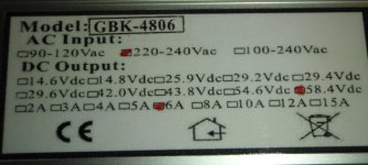
Hi, I recently bought a charger from greenbikekit.com That was suppose to be 48v. For some reason I ended up with a 24v charger instead (probably my fault since I was also ordered a 24v battery and a smaller 24v charger at the same time). Since it looks like the chargers are pretty much the same I was thinking it might be possible to convert the 24v charger into a 48v charger. The charger is marked 29.2Vdc and 12A, it needs to be 58.4vdc and 6A.
Is this possible?
lable-24vcharger.JPG

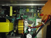
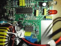
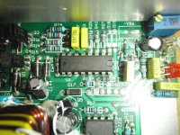
I notice 3 pot meters. One is marked EMC-400 (it might be the board number and not the pot name though, the empty pot space beside it is marked VR4) and is 5k (502). Two others are 1k (102), one of those is marked VR3 and the other has its marking covered by white glue.
inside-24vcharger.JPG
 
Most likely it can't be adjusted that much. There are some threads and a wiki entry listing some mods and some threads, for various chargers and mods. Yours (or something similar) might be among them, to tell you which pot does what.
 
dnmun said:
why don't you tell them to send you the charger you ordered?
It was my mistake, not theirs. I accidentally ordered two 24v chargers instead of one 48v and one 24v.

I just remembered that I know a person with the 48v version so I can probably borrow that and compare them and see if there's more to it than the pots. If it's not I might be able to measure the pots too.
 
Look at capacitors as one indicator.
Usually easier to go down in voltage than go up though. There may be zener diodes in there somewhere to or other over voltage protection circuitry.

I turned my 2kW BMS battery charger down from 148 to 84 volts and took current up from 12 to 20 ams, no problem, also turned a smaller 600W model up from48 to 58 volts, but the increase you are proposing is much bigger and in the wrong direction.


Ultimately the only way you will know for sure is either ask the supplier if it can be turned up..or just trying it.

You will soon know if it can't be done when it goes pop and stops working.

For a 48 volt supply you coudl jsut see about getting a Meanwell. Search the forum about them
 
the trimpot in the corner adjusts the voltage across a limited range. you can extend the range by changing the other resistors in the bridge that the trimpot is part of.

this is a good spot for you to go loook up the data sheet for the TL494 current controller, the 16 pin IC next to the trimpot.

resistor R27 is part of the resistor bridge, and that the feedback is on pin #2.

anyway, i have a few kingpan 48V chargers and will look for some resistor values at R27 in case the kingpan is similar enuff.

edit: on mine it is violet violet black red with grey band for tolerance. i measured it in the circuit and get 4.27-4.28kohm. 770x10^2 is 77k i thought. grey is .1% tolerance.

measure your resistor attached at pin #2.
 
lollandster said:
dnmun said:
why don't you tell them to send you the charger you ordered?
It was my mistake, not theirs. I accidentally ordered two 24v chargers instead of one 48v and one 24v.

I just remembered that I know a person with the 48v version so I can probably borrow that and compare them and see if there's more to it than the pots. If it's not I might be able to measure the pots too.

If you have 2qty 24V chargers why not wire in series to achieve 48V and double your power output as well? EDIT - double as in single 24V charger cranked up to 48V.
 
I have now opened up the 48v charger but I couldn't find any difference in them other than the current sensing shunt that is double on the 24v charger. I tried turning the pot to its max, but it stopped at 45v.

I will continue looking tomorrow if I have time. Maybe i will spot a resistor that is different.
 

Attachments

  • 48v-label.jpg
    48v-label.jpg
    45.9 KB · Views: 1,200
  • 48v-inside1.jpg
    48v-inside1.jpg
    140.5 KB · Views: 747
  • 48v-inside3.jpg
    48v-inside3.jpg
    161 KB · Views: 747
  • 48v-inside2.jpg
    48v-inside2.jpg
    245.3 KB · Views: 1,200
not sure why you don't post up a detailed picture of the 24V pcb with all the resistors included. my 48V looks identical to the 48V you have but i have no way to help you since you did not post up the picture of the 24V charger pcb.
 
dnmun said:
not sure why you don't post up a detailed picture of the 24V pcb with all the resistors included. my 48V looks identical to the 48V you have but i have no way to help you since you did not post up the picture of the 24V charger pcb.
I did in the first post above. do you need higher resolution?
 
yes, i cannot read anything on that picture. take the board out since you have to repair it anyway and take a good close up but include R9 over to R27 and include R32. that makes up the resistor divider bridge from + to ground.
 
R32, i measure 8.7kohm. i can tell that R27 is identical, and i think R9 is identical and i measured 6.61kohm so you should measure them on yours and compare the colors on R32.
 
R32 is paralleled with a capasitor so I can't get a steady reading without taking it out, but the colors look identical.
I can't get a steady reading of R9 either. If you really think they aren't identical to the 48v I can take them out and measure them, but they look identical to me.
I took a couple of new pictures in a warmer lighting to give a better color representation:

R9: This looks like Brown-Brown-Black-Red-Gray, i guess this is 8.2kohm (reading the colors the other way)
R9-24v.jpg

R32: Looks like Brown-Black-Black-Red-Brown=10kohm.
R32-24v.jpg
 
why can't you measure them where they are and see if they match my measurements. if there is no difference not much else to say. that is the resistor divider as you can see by following the traces on the underside.
 
dnmun said:
why can't you measure them where they are and see if they match my measurements. if there is no difference not much else to say. that is the resistor divider as you can see by following the traces on the underside.
I just told you, I can't get a steady reading because of the capacitors in parallel.
 
I took a new reading and waited for the caps to get charged and the R32 started to slow down at around 9kohm, and the r9 at about 5.9kohm. They might go even higher if I wait longer.
 
pick up one end of R32 and add about 40k in series by soldering one lead into the through hole and tie the other legs together standing up. see how far that goes. i have orange for the first color and i think that is violet. it may not need that much.
 
dnmun said:
pick up one end of R32 and add about 40k in series by soldering one lead into the through hole and tie the other legs together standing up. see how far that goes. i have orange for the first color and i think that is violet. it may not need that much.
I tried this and the voltage went up to 47v but the pot stopped doing anything. I then tried an even higher resistor at 69k and it was still only 47v. I guess there is something else that limits the voltage? I don't pretend to know how switching power supplies work, but the transformer has a sticker on it 2420T and that is not the same sticker as on the 48v version. The 48v sticker was damaged though so I don't know the whole number, but the part still there didn't match.
 
this is what heath talked about. the windings are for specific range of output voltages. looks like you will have to use a 24V power supply in series with the 24V charger.

what was the resistor value of R32 when you unsoldered one end? i saw orange, you seemed to have violet. but it may be brown.
0k.
 
dnmun said:
this is what heath talked about. the windings are for specific range of output voltages. looks like you will have to use a 24V power supply in series with the 24V charger.
Ok. Bummer. Too bad I don't need a 36v charger though as that seams to be in range (without testing with load).

Hooking up a 24v power supply in series sounds like a cheap and easy solution, but not very neat and tidy. Luckily this was a cheap charger at less than 50USD. If it wasn't so damn noisy I could probably re-purpose it as a power supply for something else.

The 24v battery I have is headway 38120 so it can take 12A charging current, but the 48v battery I use in series only has a 2A charger at the moment so there is no reason to ever use this charger (I don't think the controller works at 24v).

Maybe I can sell this one.
 
using a power supply in series is actually ok. on mine, i just bolted the charger to the top of the meanwell clone and ran the connections internally and have only the charger plug coming out with the 80v on it for the 22S pack.

you can adjust the current down if it is too much for your pack. 20A would be a lot unless it is a 20Ah pack.

but you have some range of power supplies you could choose to add, from 12V up to24V.
 
dnmun said:
using a power supply in series is actually ok. on mine, i just bolted the charger to the top of the meanwell clone and ran the connections internally and have only the charger plug coming out with the 80v on it for the 22S pack.

you can adjust the current down if it is too much for your pack. 20A would be a lot unless it is a 20Ah pack.

but you have some range of power supplies you could choose to add, from 12V up to 24V.
Thanks. Maybe it can be done more tidy than the setup I had in my head. But the current wouldn't be 20A with two 12A chargers in series (unless my electrical knowledge is far below what I thought). Never the less I would want to limit it to 6A so it isn't faster than it needs to be (that way both the 24v and the 48v pack will finish at the same time).

Correct me if I'm wrong, but the charging current would be limited by weakest power supply right? There aren't too many power supplies with adjustable current, at least not cheap ones. So I would only be able to limit the current on the charger.
 
yes, you use the charger to limit the current flowing through the power supply. it is not hard to adjust. usually the power supply will actually deliver more power for a short time, the rating is for continuous.
 
Back
Top