Minimalist BMS

erth64net

100 W
Joined
Sep 4, 2008
Messages
105
Location
Portland, OR
Searching through the forums, I can see that Lee Hart is well known...although not much has been discussed about his minimalist battery regulator design that integrates just a visual indicator, resistors and a few zener diodes.

For my initial test case, I'm considering use of 2.4V 500mW zener diodes to serve as an over-voltage bypass on a 6 cell / 15V Maxwell BCAP0010 pack. A diode would be connected to each cell, in reverse polarity of-course.

As long as the charging device properly limits current to below 1A as the pack's peak voltage is reached (and each diode's breakdown voltage is reached), and as a secondary backup, I'm thinking of a simple monitoring circuit that cuts all charging power if any cell reaches 2.6V. Does this sound like a sane path?
 
Make sure you account for the temperature coefficient over the full range, in the case of the one you chose the zener voltage will go down as the temp goes up, so it is unlikely to cause overcharging. You'll need to include a resistor or something to limit current as well, those zeners are only rated for .5W, which is about 200mA at 2.4V. I usually only design for 50% of the rated power to be safe.

Read up on the TL431 ICs. They are effectively temperature compensated adjustable zeners. I'm using them in my BMS design and they're easy to work with, available everywhere, and cheap.
 
dmwahl said:
Make sure you account for the temperature coefficient over the full range, in the case of the one you chose the zener voltage will go down as the temp goes up, so it is unlikely to cause overcharging. You'll need to include a resistor or something to limit current as well, those zeners are only rated for .5W, which is about 200mA at 2.4V. I usually only design for 50% of the rated power to be safe.

Read up on the TL431 ICs. They are effectively temperature compensated adjustable zeners. I'm using them in my BMS design and they're easy to work with, available everywhere, and cheap.

In order to increase current carrying capacity, do you think its safe to use multiple zener diodes or TL431 ICs in parallel on each cell? Are you using the thermal tab on TO-252 packaged TL431's?
 
erth64net said:
dmwahl said:
Make sure you account for the temperature coefficient over the full range, in the case of the one you chose the zener voltage will go down as the temp goes up, so it is unlikely to cause overcharging. You'll need to include a resistor or something to limit current as well, those zeners are only rated for .5W, which is about 200mA at 2.4V. I usually only design for 50% of the rated power to be safe.

Read up on the TL431 ICs. They are effectively temperature compensated adjustable zeners. I'm using them in my BMS design and they're easy to work with, available everywhere, and cheap.

In order to increase current carrying capacity, do you think its safe to use multiple zener diodes or TL431 ICs in parallel on each cell? Are you using the thermal tab on TO-252 packaged TL431's?

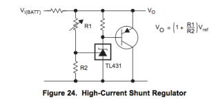
I'm not using the thermal tab, I'm actually using the SOT23 package myself (surface mount, tiny). In my BMS the 431 triggers a transistor that carries most of the current. You would probably be fine adding zeners in parallel, but you would have to take the tolerance into account then as well. Regardless it's a good idea to control the current somehow. If you're going to be using that many parts, you might as well use a 431 and power resistor. The default trigger point is 2.5V on the TL431 and is temperature compensated, so you could get by without a voltage divider and just tie the ref pin to the cathode of the 431 for your application. Should be possible with only a few parts, take a look at the high current shunt regulator in TI's datasheet for a starting point.

Check out my modular bms thread, I'll be posting schematics once I'm confident it works properly. Might give you some ideas.
 
dmwahl said:
...take a look at the high current shunt regulator in TI's datasheet for a starting point.

Check out my modular bms thread, I'll be posting schematics once I'm confident it works properly. Might give you some ideas.

Thanks for the heads-up on your BMS thread.

For the lurkers, the regulator schematic can be found on page 29 of the spec sheet. Also included here for long-term reference:
 

Attachments

  • Screen Shot 2013-05-02 at 2.50.07 PM.png
    Screen Shot 2013-05-02 at 2.50.07 PM.png
    6.5 KB · Views: 1,000
erth64net said:
dmwahl said:
...take a look at the high current shunt regulator in TI's datasheet for a starting point.

Check out my modular bms thread, I'll be posting schematics once I'm confident it works properly. Might give you some ideas.

Thanks for the heads-up on your BMS thread.

For the lurkers, the regulator schematic can be found on page 29 of the spec sheet. Also included here for long-term reference:

You've got the crowbar circuit shown there, that will drain your caps down to 0 since the triac will continue to conduct until they're empty. The circuit above with the BJT is the one you want.
 
dmwahl said:
You've got the crowbar circuit shown there, that will drain your caps down to 0 since the triac will continue to conduct until they're empty. The circuit above with the BJT is the one you want.

Eeek! Alright - I've edited the original posting and corrected the image. Thanks for catching that.
 
Back
Top