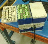
Battery assembly kit for 18650 cells - first prototype

circuit

100 kW
Joined
Mar 19, 2009
Messages
1,323
Location
EU
>> SELL THREAD <<

I am looking into using 18650 cells for some time now: link 1, link 2, link 3, link 4 (please use google translate for these). Results are stunning: 18650 cells, even with air gaps between them, offer TWICE higher capacity for volume and weight, compared to A123 20Ah pouch cells. And cheaper, too.
So after all that, probably there is no doubt that this is the way to go. However there is one major flaw: assembly complexity. This prevents 18650 from being used in hobby projects...

So here comes my project in.

Pack's configuration is 12s6p. Reasons are pretty simple:
* 48V power supplies (MeanWell for example) can be adjusted up by +10%, which gives us 52.8V. LG D1 cells are 4.35V, which gives us 52.2V in 12s configuration.
* Single cell is around 10Wh, which gives us 720Wh total capacity in 12s6p configuration. I think this is an average need of more serious ebiker.

Features
* Spot-welding
* low part count
* cell-level fuses with adjustable trip current (prevents fires in case of external or internal short)
* fuses on balancing wires (prevents fires due to shorted balancing wires or BMS)
* thermal management-ready (forced air channels)
* possibility to replace one cell without taking apart whole pack
* small size and weight

More details on assembly and single cell replacement procedures can be found on my blog (you will need google translation):
http://e-motion.lt/2013/12/12/akumuliatoriaus-blokas-is-18650-cilindriniu-celiu/
 
I was able to find a couple local companies that were able to CNC-mill the plastic trays:

IMG_20140114_190030_044.jpg

If anyone interested, please PM me.
 
I like what I see in your drawings there, nicely done, it makes for a very neat package. And I love the safety features like the fuses on the balancing wires but I wonder about the fuses on the cells. I've shorted more than one tool battery pack when trying to disassemble them too fast and the shorted cell vents but never a fire. The only damage to surrounding cells were torn shrinks from the heat. (bring on the links to all the catastrophic lipo fires that happened in the world that are not really relevant to these cells) :)

I'm just wondering what happens if one of those fuses blow for whatever reason, not that I think they would but what if, how do you replace that one fuse? Or just that one cell?

I wish I could buy a kit and be a beta tester but my ride is more of a 20S20P kind of thing. Are there ways to make this kit more modular? So that we can build different configurations?

Ray

P.S.: Edited for grammar and also to say that I edited for grammar.
 
This is good stuff. Now people will jump in saying that they need something that does not require spot welding or soldering:) You could post a rendering of the laser cut tab assembly as well. Dimensions would help here.
Whats the calculated fuse rating on series link?; For single cell?
What material for cell holder? Laser cut nickel sheet for tab assembly?
I like it
 
mistercrash said:
I like what I see in your drawings there, nicely done, it makes for a very neat package. And I love the safety features like the fuses on the balancing wires but I wonder about the fuses on the cells. I've shorted more than one tool battery pack when trying to disassemble them too fast and the shorted cell vents but never a fire. The only damage to surrounding cells were torn shrinks from the heat. (bring on the links to all the catastrophic lipo fires that happened in the world that are not really relevant to these cells) :)

I'm just wondering what happens if one of those fuses blow for whatever reason, not that I think they would but what if, how do you replace that one fuse? Or just that one cell?

I wish I could buy a kit and be a beta tester but my ride is more of a 20S20P kind of thing. Are there ways to make this kit more modular? So that we can build different configurations?

Ray

P.S.: Edited for grammar and also to say that I edited for grammar.

Individual fuses are very often overlooked. But fires do start if no fuses are used: if one cell shorts internally, it will manage itself, however in parallel blocks, it will have to handle not only itself, but also all parallel cells that will feed current into this shorted cell. This creates low-voltage and high-current "burning".
Cell can develop an internal short if it is overdischarged and recharged later on, which is probably the most popular non-mechanical cause of lithium battery fire.

To be honest I have not seen a fire involving 18650, but these are almost never used by hobbyist, so it does not count. I did see an EV with 26650 burned down to the ground. Experts concluded that it was due to covered vents and no fuses. Also, tesla uses per-cell fuses.

If one cell fuse breaks, procedure goes like this:
1. drill-out or dremel-out spot welds of whole sheet (6p cells)
2. lift off whole plastic holder
3. remove conductor sheet with damaged fuse and replace it with new one.
4. place plastic holder back and spot-weld the sheet.

To replace one cell, procedure is similar, but one should drill spot welds on both sides and only for that one cell. And one or two cells on positive side to be able to bend the sheet up and re-weld later on.
Of course drilling should be done with great care, on a well controlled drill press.


I will figure out the best way to stack larger (or smaller) packs later on, but I need to debug this one first.

agniusm said:
This is good stuff. Now people will jump in saying that they need somethinh that does not require spot welding or soldering:) You could post a rendering of the laser cut tab assembly as well. Dimensions would help here.
Whats the calculated fuse rating on series link?; For single cell?
What material for cell holder? Laser cut nickel sheet for tab assembly?
I like it
Sorry, but I just can't see a reliable and safe way to replace spot welding... I do realize this requires a special and sometime hard-to-get-hands-on tool. By the way it is not that hard to make one with a lab PSU, 2F capacitor and a few beefy FETs - I use such DIY welder with great success.

I will add dimensions tomorrow, as now my PC is doing its best on computing air flow via pack's cooling channels. 7 hours to go...

Fuse rating is not yet determined. I will cut some sample fuses of different cross section and do proper tests. For now I can tell only that it will be possible to cut one or more filaments to lower current rating. For example, if overall carrying current of one fuse is 16A, if will be possible to get 12, 8 and 4 amps with the same part.

Cell holder for first prototype will be, probably, PVC, due to low cost. PPA or similar high-temp plastic later on.
Weldable conductor: nickel (Ni2010) or nickel-plated stainless steel (for price reduction, as pure nickel is quite pricey).
 
You are smart to make the interconnects both able to distribute relative motion between cells and the interconnect board over a wide area, as well as low thermal mass to get good weld quality with less risk of blowing through and pin-holing, and the fusing option is nice as well.

I think you will find if you subject this pack to harsh vibration, the cell support feature for the can is perhaps a bit low. You must imagine an ebike battery being bounced down a road for a decade in a vehicle with no suspension moving at a good clip. Think of a structure to support the cells that can withstand being hit with a hammer repeatedly. It seems like overkill when it's sitting on your bench, but its not overkill when its bolted to a rigid rack on a rigid bicycle banging into pot-holes at 35mph.

At least that's my $0.02, and I like where the design is going. There are a few very compelling EV suitable 18650's on the market now (thank you Tesla!).
 
liveforphysics said:
I think you will find if you subject this pack to harsh vibration, the cell support feature for the can is perhaps a bit low. You must imagine an ebike battery being bounced down a road for a decade in a vehicle with no suspension moving at a good clip. Think of a structure to support the cells that can withstand being hit with a hammer repeatedly. It seems like overkill when it's sitting on your bench, but its not overkill when its bolted to a rigid rack on a rigid bicycle banging into pot-holes at 35mph.
I hear what you are saying. I do have the same concerns about mechanical stresses. One way to improve this is to make the supports higher. Currently they are 3mm (total material thickness 4mm). I could increase that to, say, 9mm, but this would tripple the price, which is not that low already. I guess I will make it as it is now and evaluate for later adjustments.

LSBW said:
6P of LG D1s is good for 18 Amp continuous and 36 Amp peak.

See here: http://endless-sphere.com/forums/viewtopic.php?f=14&t=52710

I would go for at least 10P.
Technically, 36 amp peak on battery means around 72 amp peak on motor, because, typically, ebike system power peaks out around 50% rpm.

The beauty of this kit (and 18650 cell overall) is that there is a very wide selection of cells: you could fit 5c cells in there easilly.
 
Isn't it somehow similar to this kit?http://m.ebay.com/itm?itemId=321114233041

I purchased a bunch of them to see how it works.

But I'd prefer a solution without spot welding
 
cwah said:
Isn't it somehow similar to this kit?http://m.ebay.com/itm?itemId=321114233041

I purchased a bunch of them to see how it works.

But I'd prefer a solution without spot welding
Wow, that is cheap. I saw those some time ago, but they were quite expensive.

The only similarity is that both are "trays". Molding technique gives them modular assembly capability.. And higher profile, since there is no material loss while milling.
However I don't like that solution because:
1. slightly larger overall dimensions
2. no way to replace single cell
3. no rigid support for nickel tabs - reliable fusing is not possible...

I'd prefer weld-less method as well, If there was one... Te one LSBW posted is simply a recipe for disaster and not the way to go.
 
Nice, wanted to do something similar but zero time.

Commercial 18650 cell holders in packs usually split cells into smaller groups because it's easier to handle vibration and venting
If you are going this style it's good too really have it solid structure to hold it tight as one piece.

If your interested I have access to battery factory and can fabricate some packs for trial free of charge.
Can probably ask a friend for rejected 18650 cells and not worry about destructive testing costing....
 
If its 4mm I think its a bit too thin. One solution fot this is to use exact aluminum box to almost press assembly in. This is expensive and another head ache thou. If plastic tray sides were smooth and as you mentioned 9mm thick, you could cut a sheet of say 1mm thick aluminum, bend it arround and put 3mm screws all around. Then using couple of bolts in the middle to remove flex there. Some pvc sheets could be bolted to the tray through those holes with pc fan screws(thats to make them right size on the design first) to isolate. My cheap and dirty thinking :D
 
this 12s6p config would nice fit into a peli 1170 case :)

are there any other config planned?
 
circuit said:
Not planned yet. If there will be demand, other configs will be made. Due to low interest, I think this will be a custom-designed part for most, with some small engineering fee.

this sounds reasonable to me. 12s6p is a common size for normal e-bikes. good success with the prototype.
 
I was able to find a couple local companies that were able to CNC-mill the plastic trays:

IMG_20140114_190030_044.jpg


I am also actively working with couple of laser-cutting companies for tab cutting. I have some samples cut already and the results are good (even better than expected):
IMG_20140117_100924.jpg


As you can see I still don't have tab material of proper dimensions, still waiting for it to arrive. So I did this cutting test on old narrow scrap band I found lying around (this is why it is so dirty).
I did numerous tests on current handling and adjusted material thickness and bridge width for proper trip current. So YES!! Cell-level protection is now available!

The problem is... As you can see, I only have 6 cells :) I do have some inbound, but only in like 2-3 months :(
 
Congrats, looks really good. Have you got thicker material in the end? Four sides of the bracket could be flat, some milling time could be saved perhaps slightly better rigidity achieved. Don't estimate shipping, back to who ever buys the kit at 10-15. EU also has ADR Class 9 which bumps up the cost.
 
Yes, this is 10mm plastic.
Shipping prices are just a quick idea on what it *might* cost. I assume that my first customer will be in European Union to avoid high shipping costs (for example, cheapest shipping to USA is ~$70). Also to avoid problems with customs, as I will have nothing to give them as an "invoice" for cell "purchase".
But of course, if someone is ready to pay large for shipping, request from anywhere is welcome.
 
Allex said:
Nice kit. How will some one replace one bad cell in the middle? Do you have to open the whole kit?
I don't know what you mean by "open the whole kit". But roughly it goes like this:
1. Find a bad cell.
2. drill-out or dremel-out it's spot welds by preserving as much tabs as possible
3. remove plastic tray from one side of the pack.
4. replace the cell
5. place plastic tray back on
6. spot weld new cell in place.

Maybe not very friendly method, but probably the best I come up with. And I don't know if easier way exists.
 
Back
Top