Another Charger Voltage Mod Question.

drutledge

10 W
Joined
Mar 28, 2011
Messages
81
Location
Washington, DC
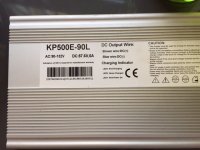
I purchased a 500W (KP500E) charger off of ebay last year. I was hoping it would conform to the basic BMS Battery configurations which I've modified before but this one has a different layout. This charger also has the 'no output without battery hooked up' feature so monitoring voltage change is hard. Someone mentioned reading the voltage off of the cap legs. I assume they would mean the cap nearest the relay in my photos. Correct? I honestly don't feel like sticking probes into a running charger but...

Any guidance as to what each of the three pots in this charger do would be greatly appreciated.

View attachment 2

View attachment 1
IMG_7566.JPG
 
Interesting... Following, I'd like to learn about this too.
 
dnmun said:
the trimpot next to pin#1 on the TL494 is the one used to adjust the output voltage. do not adjust either of the other two.

Thanks. Any idea what the other two do? I'm sure I've turned them in the past (and attempted to put them back into the same spot).
 
If one wanted a lower output voltage from a charger (say 54V instead of 59V), and the charger didn't have any pot to adjust, is it feasible to add a resistor or pot inline in the output cable of the charger to deliver the lower voltage to the battery pack?

Anyone done this? Or is it just not a good idea?

I would assume that for a drop of 5V with a 2.5 amp charger, one would need a resistor of 2 ohms?
 
dilkes said:
If one wanted a lower output voltage from a charger (say 54V instead of 59V), and the charger didn't have any pot to adjust, is it feasible to add a resistor or pot inline in the output cable of the charger to deliver the lower voltage to the battery pack?

Anyone done this? Or is it just not a good idea?

I would assume that for a drop of 5V with a 2.5 amp charger, one would need a resistor of 2 ohms?

NO - it would burn up. Make a daughter board for pin #1 of the TL494 and use a 10 turn pot, that will give you adjustability.

PS: One of the other two pots is current limit, you will need to turn it down if you turn the voltage up or POOF you can also likely turn it up if you lower the voltage - the idea is get it to the point where maximum voltage X Current Limit = Rated Wattage.

Hope this helps a bit more!

-Mike
 
the other two are for adjusting the maximum current that the charger pushes to prevent it from overheating, and the other trimpot adjusts set point where the current crops to a low enuff level that it causes the charger to go into the balancing phase and turn off the charging led and fan. but still trickles the balancing current as it climbs up to the final voltage.

without looking at the pcb and seeing which of the trimpots is in parallel with the shunt wire there i cannot distinguish between them.

you can try charging with it and then adjust the one farther away from the shunt first and see if the output current changes as measured through your wattmeter. you can adjust the current to 6-7A and then when the charging voltage reaches close to full voltage, watch the charging current and when it drops to about 200-250mA then adjust the other trimpot so the led and fan turns off.

you have to adjust the maximum charging current at the beginning of charging when the difference in uncharged pack voltage and the final set voltage of the charger is max.
 
Back
Top