battman
1 W
Hi Folks,
Motivation for this project was similar to the MAX11081 BMS I put together last year (http://www.endless-sphere.com/forums/viewtopic.php?f=14&t=56937&p=849127&hilit=max11081#p849127), namely bad experience with commercial BMS and looking for something simple enough that I could build and tinker with.
The MAX14920 based BMS presented here is cheap (about $50 in parts for a 12 cell implementation), relatively simple to build and has the following features:
Since it's controlled by a Picaxe, behavior is highly customizable. Current draw is 0.22mA quiescent and 1.2mA during discharge, i.e. vehicle operational.
The BMS Data Uploader displays BMS configuration and cell voltages on a PC via the Picaxe serial cable. WARNING!!! Not isolated!!!
Corrections, suggested improvements etc. all welcome. I'm a software engineer, so input from electrical engineers would be good, especially if there are safety related concerns with any aspects of the project.
Main Board
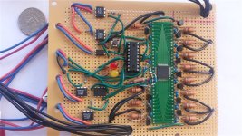
Mouser Project:
http://www.mouser.com/ProjectManager/ProjectDetail.aspx?AccessID=dc4e5c0df4
In addition to the parts listed in the Mouser project, you will need:
and if you don't have one, then you'll need to beg, borrow or steal an AXE027 USB-to-serial Picaxe programming cable. Since I built this BMS, I have noticed an apparently better QFP adapter from SchmartBoard (part number 872-204-0018-01) available through Mouser. It's several dollars cheaper than the one I used, it has a hole in the middle that should allow decent heatsinking (important for being able to balance as many cells as possible simultaneously), and will also save on shipping costs if the other parts are being ordered from Mouser at the same time.
Picaxe Source Code:
http://sourceforge.net/projects/max14920bms/files/PicaxeSupervisor/
Perfboard Layout:
View attachment cad_max_14920_bms_main_v1.2.pdf
Schematic:
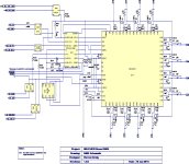
Configuration:
Pressing the USER_CMD momentary switch for more than four seconds, then releasing puts the BMS into configuration mode. It auto-detects the number of connected cells and auto-selects cell chemistry (and hence suitable LVC and HVC values) from average cell voltage. I was just playing around with this idea and might just change this to manual selection at a later date. Then it flashes the user to manually select the charge mode; terminate charge on first cell HVC, or balance cells at end of charge. Then open wire detection is performed. The full sequence of interactions goes like this:
Notes:
The two main sources error on reading a cell voltage are the 10 bit accuracy of the Picaxe ADC and the MCP606-I/P voltage divider/ voltage buffer circuit. If a maximum of 4.05V is sufficient for a particular implementation, for example, if only using LiFePO4 cells, then the voltage divider circuit may be eliminated. The K_CELL_V*** voltage constants in the Picaxe code will then need to be adjusted along with the Cell.adcToVoltageScaling constant in the BMS Data Uploader Cell.cs C# file.
The MAX14920 flows an internal balancing current of 10mA per cell that is being balanced. I had been unable to successfully heatsink the MAX14920 using the EZPrototypes QFP adapter in this perfboard implementation, so I have limited balancing to a maximum of 4 cells simultaneously. Balancing current is about 0.25A with the BS170 mosfet and 15R resistor combination. Higher balance currents are possible with different transistor and resistor selection. The transistor should be a logic level N-channel FET. Higher balance currents may warrant reduction of the Picaxe constant K_BLEED_CHARGE_SECONDS. If balancing is not required then the balancing resistors and transistors can be eliminated from the build. Note that since I did this build, I found a better adapter from SchmartBoard that is both cheaper and makes decent provision for heatsinking. The EZPrototypes adapter can't even be drilled under the location of the chip's ground pad because they placed traces right at that location on the underside of the adapter - bad design.
The MAX14921 chip could be substituted for the MAX14920, an appropriate 600mil adapter obtained for it, and the perfboard extended a bit and then 16 cells could be managed by a single board ... with two important caveats; a) both chips have a maximum voltage rating of 65V, so it would be tough supporting LiPo since 16 of those cells in series would exceed 65V unless you were prepared to be very conservative with maximum cell voltage, and b) maximum power dissipation of the MAX14921 is curiously lower than the MAX14920, so you'd be able to balance even fewer of them simultaneously!
With the Picaxe clock speed at default 4Mhz and 12 connected cells, then LVC is checked for all cells about 4 times per second. If this isn't fast enough, then the Picaxe clock speed may be increased, but note that some timing values in the code will need to be altered (any related to 'pause' or 'time' in the code) and that power consumption will increase. Doubling clock speed to 8Mhz sees an almost doubling of current consumption from 1.2mA to 2.3mA but does also allow 8 checks per second. Increasing clock speed massively, e.g. to 32Mhz, may result in other unwanted effects showing up, possibly due to parasitic capacitance in circuit or additional timing requirements in the code such as when switching between sample and hold phase on the MAX14920.
Building and Testing:
Start by adding the Picaxe and associated 10K, 22K resistors and 3.5mm stereo phone jack. Temporarily power this from a supply somewhere between 3 and 5 volts. Now verify correct Picaxe operation by attempting to download a short program to it, e.g. Just a single line “b0=0”.
Add the QFP to 600 mil DIP Adapter to the board and solder the MAX14920 chip to it. Make sure none of the chips pins are bent. One of the chips I received had one corner pin bent and touching another. This tiny SMD part, bristling with pins, looks a little daunting to solder at first. There are good videos on youtube on how to solder SMD parts and it really isn't that bad. Tools I found helped were a magnifying glass, a flux pen and solder braid to clean up any solder bridges. Go over each pin with a multimeter and make sure adjacent pins aren't shorted and that all pins are electrically connected to the corresponding adapter pins. If you are using an adapter from a source other than EZ prototypes, the chip to adapter pin layout could be completely different!
Now add parts to allow minimal operation of the MAX14920. Do not add balancing circuitry yet. Do not add connections between the MAX14920 and the Picaxe yet. Add all the cell taps. Connect cells to the lowest 3 taps and short all the other cell taps together and then short that group to the +ve of the 3rd cell. The MAX14920 should now power up correctly. If it does, there will be 5V at the VA pin.
Add the MCP606-I/P and voltage divider resistors. Do not connect the 5.62K divider resistor to the AOUT pin yet. Connect the CHG and BAL LEDs and the USER_CMD button to the Picaxe. Upload the supplied test_voltage_measurement.bas code to the Picaxe. Connect a known voltage to the AOUT end of the 5.62K pin and connect the ground of that voltage to the AGND side of the 100K resistor. Follow the instructions in the Picaxe basic file and verify voltage measurements are read correctly.
Add all remaining parts except the cell balancing resistors and transistors. Ensure the SPI connections have been made between the Picaxe and the MAX14920. Use the supplied test_input.bas and test_output.bas to verify correct opto-isolator operation.
Add the balancing circuitry and cells to the remaining cell taps so the BMS is operating at full voltage. Upload the test_balancing.bas program. Run the BMS Data Uploader program on the PC, ensure the Picaxe AXE027 serial cable is connected between the PC and BMS and set it to upload data from the Picaxe. Press the USER_CMD button and verify cell balancing is occurring on the cell that is displayed yellow in the BMS Data Uploader. If a cell is balancing correctly, then there will be an approximately 0.5V drop across the balance resistor. An alternative measurement that avoids placing voltmeter leads near the live circuitry and causing an accidental short is to use an IR thermometer placed close to the balance resistor. There should be a temperature rise of several degrees Fahrenheit.
Charge Control
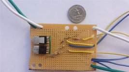
Mouser Project:
http://www.mouser.com/ProjectManager/ProjectDetail.aspx?AccessID=f2f9ad0c8f
Perfboard Layout:
View attachment cad_max_14920_chg_control.pdf
Schematic:
View attachment 2
Notes:
Charging currents of up to 15A are possible with no additional heatsinking on the PSMN5R0-80PS. The circuit is good for 12V-72V as-is. Different mosfets and resistances will be required for charging at higher voltages than that.
PSMN5R0-80PS are configured in an "SSR" like configuration to ensure that current cannot flow from the battery back towards the charger when charging is disabled. Zener D1 and R3 ensure that a maximum of 18V is applied to the PSMN5R0-80PS gates when CHG_EN is enabled. Maximum will actually be a little less than 18V anyways due to the voltage drop across the CHG_EN LDA111 opto-coupler output. When ALL_CELL_BAL is enabled, this overrides CHG_EN and disables charging. The selection of resistor R2, R3 and R4 values ensures this strong pulldown behavior. CHG_EN could be used to control charging without ALL_CELL_BAL (with some changes to the Picaxe code) if only a single BMS board (no stacking) is used, or if the charge mode is set to stop when the first cell hits HVC. But for a stacked configuration with balancing, individual boards cannot disable charging completely. Their ALL_CELL_BAL outputs are 'anded' together to only completely disable charging when every module has finished balancing all it's cells.
Testing:
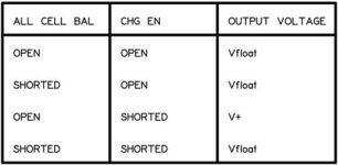
To test the charge control circuit, connect a power supply of between 24 and 72 volts to the charger inputs. Connect a voltmeter to the charge control circuit outputs. Call the power supply voltage V+ and call a low floating voltage somewhere in the sub 1V range, Vfloat. A correctly functioning charge control circuit will conform to the following table.
BMS Data Uploader
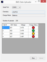
Warning!!!! There is no voltage isolation between the BMS main board and the PC when connected by the AXE027 USB-to-serial cable in this implementation.
The traffic light icons have tooltips describing the associated color. A hollow white circle is in-active/ not charging. Red is charging. Yellow is balancing and green is fully charged.
To upload data, connect the Picaxe serial cable to the PC and BMS. Start the program, select the serial port and press 'Upload'. Then either press the USER_CMD momentary pushbutton for less than 4 seconds. A single dataset will be uploaded. Alternatively, connect a charger and start charging. Uploads will be sent continually to the PC indicating charging progress.
C# Source Code:
http://sourceforge.net/projects/max14920bms/files/DataUploader/
The free version of Microsoft Visual Studio, Visual Studio Express, may be used to build the BMS Data Uploader. I used Visual Studio Express 2013.
Stacking
View attachment cad_max_14920_bms_stacking.pdf
Let me first get off my chest that I haven't had a chance to test the stacking capability yet. Whew, feel better now. Modules are stacked by:
How many modules can be stacked?
I think there are at least three limiting factors involved:
Often, the LVC 5V current will be taken from the controller 5V throttle output (which is actually 4.4V if an Infineon controller is used). Your mileage may vary on this one. If we assume that we don't want the base voltage of the turned on charging mosfets to be less than 10V, then that would lead to a stack limit of 11 modules. The optos have isolation voltages in the multiple thousands of volts, so this appears not to be a factor here.
These are just some initial thoughts, my electrical knowledge is feeble enough that there are likely other factors. At some point I'll get round to building a small stack just to make sure the basic operation matches what I designed.
Motivation for this project was similar to the MAX11081 BMS I put together last year (http://www.endless-sphere.com/forums/viewtopic.php?f=14&t=56937&p=849127&hilit=max11081#p849127), namely bad experience with commercial BMS and looking for something simple enough that I could build and tinker with.
The MAX14920 based BMS presented here is cheap (about $50 in parts for a 12 cell implementation), relatively simple to build and has the following features:
- HVC (accuracy 0.01V)
- LVC (accuracy 0.01V)
- Open-wire detection
- Balancing
- Stackable
- Semi-automatic configuration
- BMS Data Uploader
Since it's controlled by a Picaxe, behavior is highly customizable. Current draw is 0.22mA quiescent and 1.2mA during discharge, i.e. vehicle operational.
The BMS Data Uploader displays BMS configuration and cell voltages on a PC via the Picaxe serial cable. WARNING!!! Not isolated!!!
Corrections, suggested improvements etc. all welcome. I'm a software engineer, so input from electrical engineers would be good, especially if there are safety related concerns with any aspects of the project.
Main Board

Mouser Project:
http://www.mouser.com/ProjectManager/ProjectDetail.aspx?AccessID=dc4e5c0df4
In addition to the parts listed in the Mouser project, you will need:
- Picaxe 18m2+. I used Sparkfun
- 64 Pin .5 mm (10x10) QFP to 600 mil DIP Adapter. I used ezprototypes.com
- N.O. momentary pushbutton switch. I used Radio Shack
- 3.5mm stereo phone jack. I used Radio Shack
and if you don't have one, then you'll need to beg, borrow or steal an AXE027 USB-to-serial Picaxe programming cable. Since I built this BMS, I have noticed an apparently better QFP adapter from SchmartBoard (part number 872-204-0018-01) available through Mouser. It's several dollars cheaper than the one I used, it has a hole in the middle that should allow decent heatsinking (important for being able to balance as many cells as possible simultaneously), and will also save on shipping costs if the other parts are being ordered from Mouser at the same time.
Picaxe Source Code:
http://sourceforge.net/projects/max14920bms/files/PicaxeSupervisor/
Perfboard Layout:
View attachment cad_max_14920_bms_main_v1.2.pdf
Schematic:

Configuration:
Pressing the USER_CMD momentary switch for more than four seconds, then releasing puts the BMS into configuration mode. It auto-detects the number of connected cells and auto-selects cell chemistry (and hence suitable LVC and HVC values) from average cell voltage. I was just playing around with this idea and might just change this to manual selection at a later date. Then it flashes the user to manually select the charge mode; terminate charge on first cell HVC, or balance cells at end of charge. Then open wire detection is performed. The full sequence of interactions goes like this:
- Press USER_CMD for > 4 seconds. CHG LED stays lit while pressed.
- CHG LED flashes once if LiFePo4 chemistry detected. Twice if Lipo detected. Detection is based on threshold voltage.
- BAL LED flashes N times for N connected cells. If no cells are detected (could happen if end connections are OK but intermediate taps are messed up), solid CHG and BAL LEDs are displayed for 8 seconds.
- 4 second pause.
- Balance LED flashes rapidly indicating user must select charge mode.
- Press USER_CMD for <= 4 seconds to select first cell HVC mode, > 4 seconds to select balance mode.
- If first cell HVC mode is selected, then CHG LED is displayed solid for 1 second. If balance mode is selected then BAL LED is displayed solid for 1 second.
- Open wire detection is performed. If an open wire is detected, then CHG and BAL LEDs are flashed together X times, where X is the number of the cell where an open wire was detected. This flashing occurs at 15 second intervals until USER_CMD is pressed to continue. After this is pressed, or no open wire was detected, configuration is considered complete.
Notes:
The two main sources error on reading a cell voltage are the 10 bit accuracy of the Picaxe ADC and the MCP606-I/P voltage divider/ voltage buffer circuit. If a maximum of 4.05V is sufficient for a particular implementation, for example, if only using LiFePO4 cells, then the voltage divider circuit may be eliminated. The K_CELL_V*** voltage constants in the Picaxe code will then need to be adjusted along with the Cell.adcToVoltageScaling constant in the BMS Data Uploader Cell.cs C# file.
The MAX14920 flows an internal balancing current of 10mA per cell that is being balanced. I had been unable to successfully heatsink the MAX14920 using the EZPrototypes QFP adapter in this perfboard implementation, so I have limited balancing to a maximum of 4 cells simultaneously. Balancing current is about 0.25A with the BS170 mosfet and 15R resistor combination. Higher balance currents are possible with different transistor and resistor selection. The transistor should be a logic level N-channel FET. Higher balance currents may warrant reduction of the Picaxe constant K_BLEED_CHARGE_SECONDS. If balancing is not required then the balancing resistors and transistors can be eliminated from the build. Note that since I did this build, I found a better adapter from SchmartBoard that is both cheaper and makes decent provision for heatsinking. The EZPrototypes adapter can't even be drilled under the location of the chip's ground pad because they placed traces right at that location on the underside of the adapter - bad design.
The MAX14921 chip could be substituted for the MAX14920, an appropriate 600mil adapter obtained for it, and the perfboard extended a bit and then 16 cells could be managed by a single board ... with two important caveats; a) both chips have a maximum voltage rating of 65V, so it would be tough supporting LiPo since 16 of those cells in series would exceed 65V unless you were prepared to be very conservative with maximum cell voltage, and b) maximum power dissipation of the MAX14921 is curiously lower than the MAX14920, so you'd be able to balance even fewer of them simultaneously!
With the Picaxe clock speed at default 4Mhz and 12 connected cells, then LVC is checked for all cells about 4 times per second. If this isn't fast enough, then the Picaxe clock speed may be increased, but note that some timing values in the code will need to be altered (any related to 'pause' or 'time' in the code) and that power consumption will increase. Doubling clock speed to 8Mhz sees an almost doubling of current consumption from 1.2mA to 2.3mA but does also allow 8 checks per second. Increasing clock speed massively, e.g. to 32Mhz, may result in other unwanted effects showing up, possibly due to parasitic capacitance in circuit or additional timing requirements in the code such as when switching between sample and hold phase on the MAX14920.
Building and Testing:
Start by adding the Picaxe and associated 10K, 22K resistors and 3.5mm stereo phone jack. Temporarily power this from a supply somewhere between 3 and 5 volts. Now verify correct Picaxe operation by attempting to download a short program to it, e.g. Just a single line “b0=0”.
Add the QFP to 600 mil DIP Adapter to the board and solder the MAX14920 chip to it. Make sure none of the chips pins are bent. One of the chips I received had one corner pin bent and touching another. This tiny SMD part, bristling with pins, looks a little daunting to solder at first. There are good videos on youtube on how to solder SMD parts and it really isn't that bad. Tools I found helped were a magnifying glass, a flux pen and solder braid to clean up any solder bridges. Go over each pin with a multimeter and make sure adjacent pins aren't shorted and that all pins are electrically connected to the corresponding adapter pins. If you are using an adapter from a source other than EZ prototypes, the chip to adapter pin layout could be completely different!
Now add parts to allow minimal operation of the MAX14920. Do not add balancing circuitry yet. Do not add connections between the MAX14920 and the Picaxe yet. Add all the cell taps. Connect cells to the lowest 3 taps and short all the other cell taps together and then short that group to the +ve of the 3rd cell. The MAX14920 should now power up correctly. If it does, there will be 5V at the VA pin.
Add the MCP606-I/P and voltage divider resistors. Do not connect the 5.62K divider resistor to the AOUT pin yet. Connect the CHG and BAL LEDs and the USER_CMD button to the Picaxe. Upload the supplied test_voltage_measurement.bas code to the Picaxe. Connect a known voltage to the AOUT end of the 5.62K pin and connect the ground of that voltage to the AGND side of the 100K resistor. Follow the instructions in the Picaxe basic file and verify voltage measurements are read correctly.
Add all remaining parts except the cell balancing resistors and transistors. Ensure the SPI connections have been made between the Picaxe and the MAX14920. Use the supplied test_input.bas and test_output.bas to verify correct opto-isolator operation.
Add the balancing circuitry and cells to the remaining cell taps so the BMS is operating at full voltage. Upload the test_balancing.bas program. Run the BMS Data Uploader program on the PC, ensure the Picaxe AXE027 serial cable is connected between the PC and BMS and set it to upload data from the Picaxe. Press the USER_CMD button and verify cell balancing is occurring on the cell that is displayed yellow in the BMS Data Uploader. If a cell is balancing correctly, then there will be an approximately 0.5V drop across the balance resistor. An alternative measurement that avoids placing voltmeter leads near the live circuitry and causing an accidental short is to use an IR thermometer placed close to the balance resistor. There should be a temperature rise of several degrees Fahrenheit.
Charge Control

Mouser Project:
http://www.mouser.com/ProjectManager/ProjectDetail.aspx?AccessID=f2f9ad0c8f
Perfboard Layout:
View attachment cad_max_14920_chg_control.pdf
Schematic:
View attachment 2
Notes:
Charging currents of up to 15A are possible with no additional heatsinking on the PSMN5R0-80PS. The circuit is good for 12V-72V as-is. Different mosfets and resistances will be required for charging at higher voltages than that.
PSMN5R0-80PS are configured in an "SSR" like configuration to ensure that current cannot flow from the battery back towards the charger when charging is disabled. Zener D1 and R3 ensure that a maximum of 18V is applied to the PSMN5R0-80PS gates when CHG_EN is enabled. Maximum will actually be a little less than 18V anyways due to the voltage drop across the CHG_EN LDA111 opto-coupler output. When ALL_CELL_BAL is enabled, this overrides CHG_EN and disables charging. The selection of resistor R2, R3 and R4 values ensures this strong pulldown behavior. CHG_EN could be used to control charging without ALL_CELL_BAL (with some changes to the Picaxe code) if only a single BMS board (no stacking) is used, or if the charge mode is set to stop when the first cell hits HVC. But for a stacked configuration with balancing, individual boards cannot disable charging completely. Their ALL_CELL_BAL outputs are 'anded' together to only completely disable charging when every module has finished balancing all it's cells.
Testing:
To test the charge control circuit, connect a power supply of between 24 and 72 volts to the charger inputs. Connect a voltmeter to the charge control circuit outputs. Call the power supply voltage V+ and call a low floating voltage somewhere in the sub 1V range, Vfloat. A correctly functioning charge control circuit will conform to the following table.

BMS Data Uploader

Warning!!!! There is no voltage isolation between the BMS main board and the PC when connected by the AXE027 USB-to-serial cable in this implementation.
The traffic light icons have tooltips describing the associated color. A hollow white circle is in-active/ not charging. Red is charging. Yellow is balancing and green is fully charged.
To upload data, connect the Picaxe serial cable to the PC and BMS. Start the program, select the serial port and press 'Upload'. Then either press the USER_CMD momentary pushbutton for less than 4 seconds. A single dataset will be uploaded. Alternatively, connect a charger and start charging. Uploads will be sent continually to the PC indicating charging progress.
C# Source Code:
http://sourceforge.net/projects/max14920bms/files/DataUploader/
The free version of Microsoft Visual Studio, Visual Studio Express, may be used to build the BMS Data Uploader. I used Visual Studio Express 2013.
Stacking
View attachment cad_max_14920_bms_stacking.pdf
Let me first get off my chest that I haven't had a chance to test the stacking capability yet. Whew, feel better now. Modules are stacked by:
- ANDing ALL_CELL_BAL outputs
- ANDing CHG_EN outputs
- ANDing CHG_CON
- Oring LVC SIG outputs
- ORing LVC 5V inputs
How many modules can be stacked?
I think there are at least three limiting factors involved:
- LVC 5V current that is available.
- "Diode" voltage drop from ANDed CHG_EN outputs.
- Isolation voltage of LDA111 and LTV817 opto-isolators.
Often, the LVC 5V current will be taken from the controller 5V throttle output (which is actually 4.4V if an Infineon controller is used). Your mileage may vary on this one. If we assume that we don't want the base voltage of the turned on charging mosfets to be less than 10V, then that would lead to a stack limit of 11 modules. The optos have isolation voltages in the multiple thousands of volts, so this appears not to be a factor here.
These are just some initial thoughts, my electrical knowledge is feeble enough that there are likely other factors. At some point I'll get round to building a small stack just to make sure the basic operation matches what I designed.


