welding 18650 cells with DN-5 spot welder

madin88

10 MW
Joined
May 27, 2013
Messages
3,120
Location
Austria
Hi together,
as there is no thread about the chinese DN - type welders i have started one.
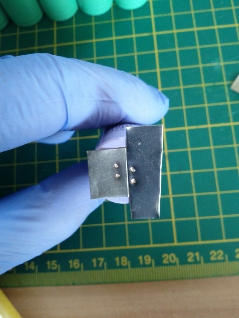
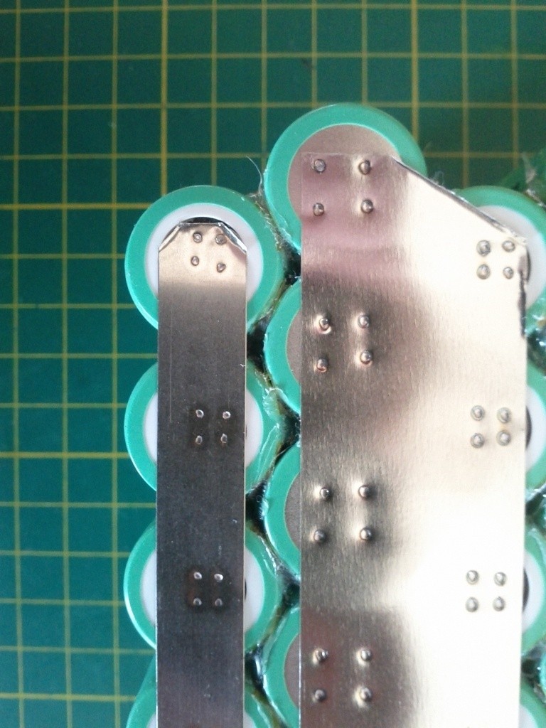
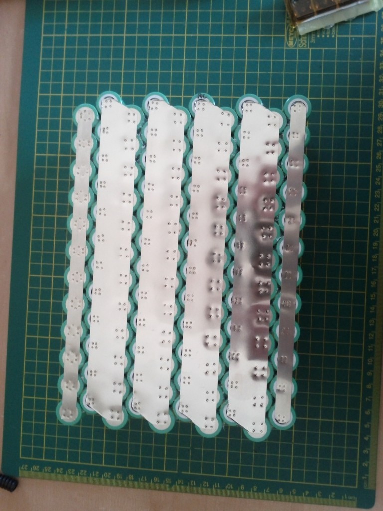
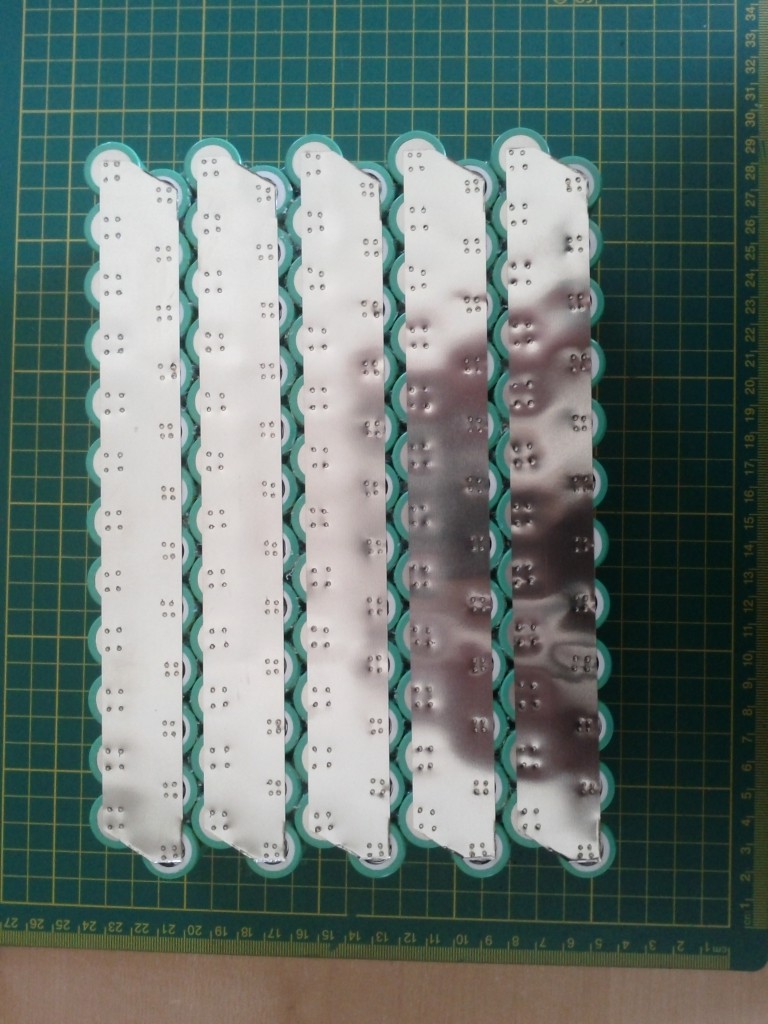
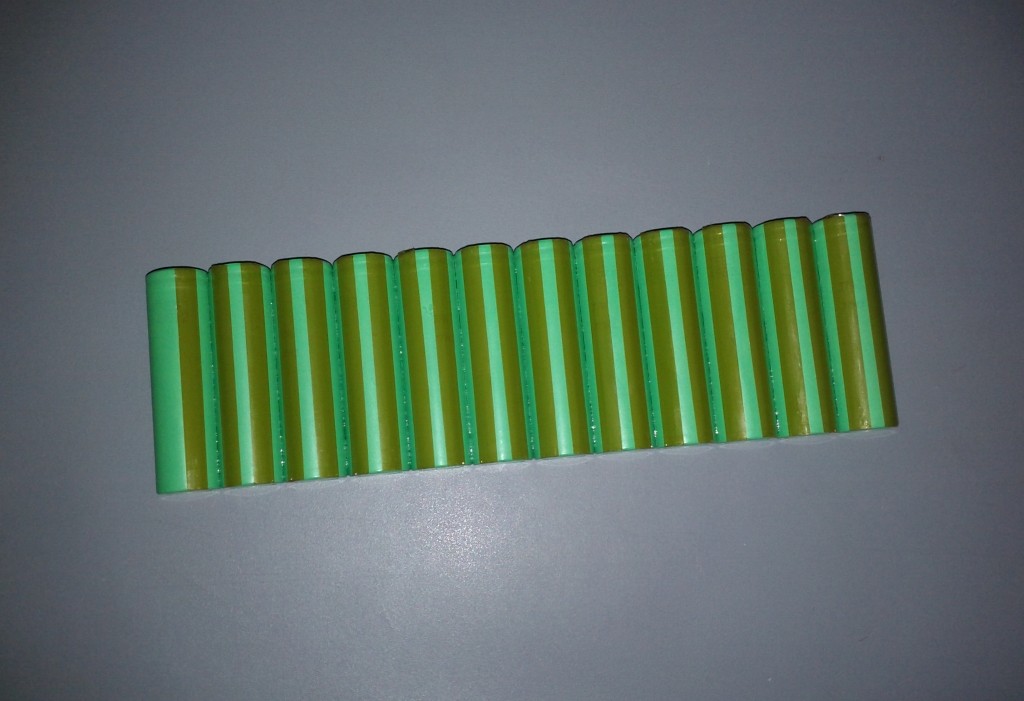
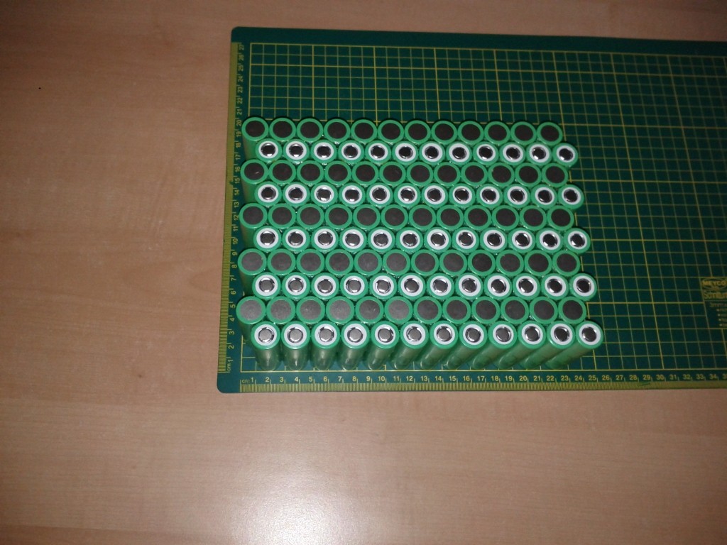
Also i will write about different materials used for welding and how i build my batteries so they hopefully last long under vibrations they need to withstand on our bikes and vehicles.

i have bought the welder from here:
http://www.cart100.com/Product/15904562609/
shipping costs to Austria have add about 200 $ beacuse this thing is really heavy. we talking about more than 20kg!

How does it work:

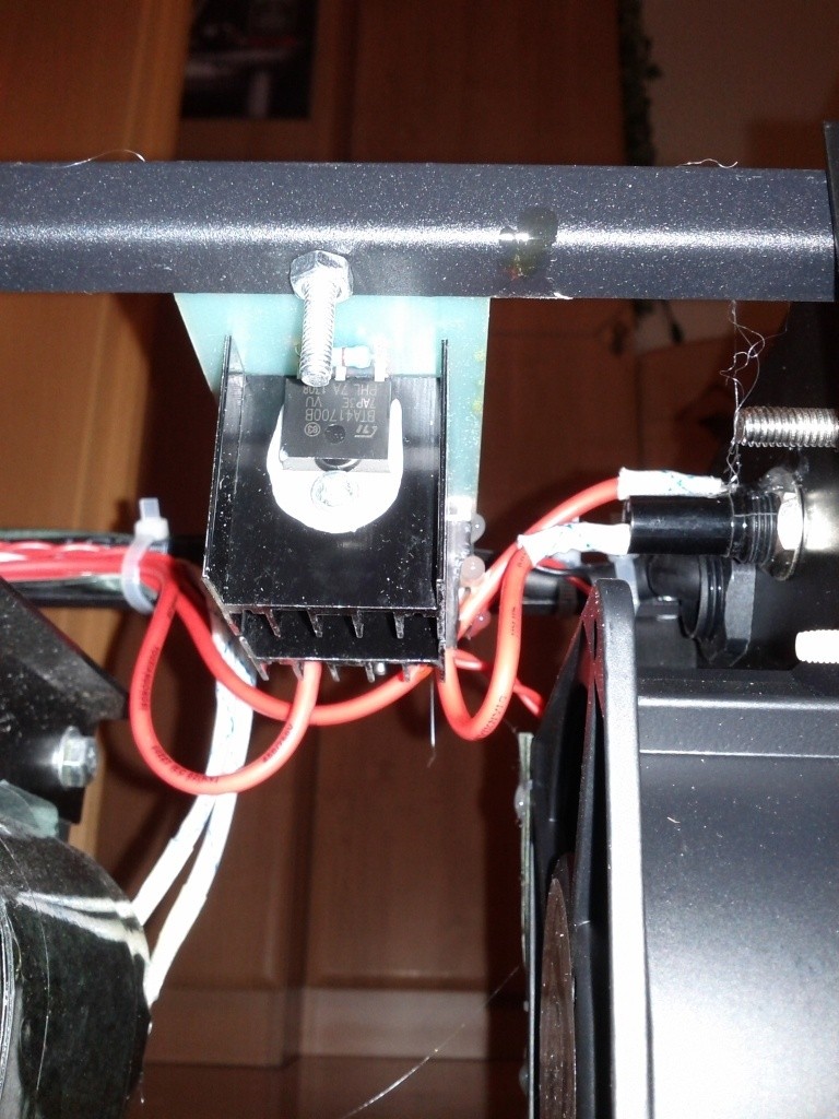
if you push the foot switch some FET's inside will close the connection between AC power and a big transformer. with the pot on the front you can set up the time how long this connection will be closed (i believe the range is between 10 - 300ms).
DN-5 means 5kW (peak) from what i know, but i had no problem to use it on nomal house socket with normal 16A fuse. Only the lights do flicker in same room but nothing to bother about :)

check the pics with descriptions (im sorry for the phone quality):
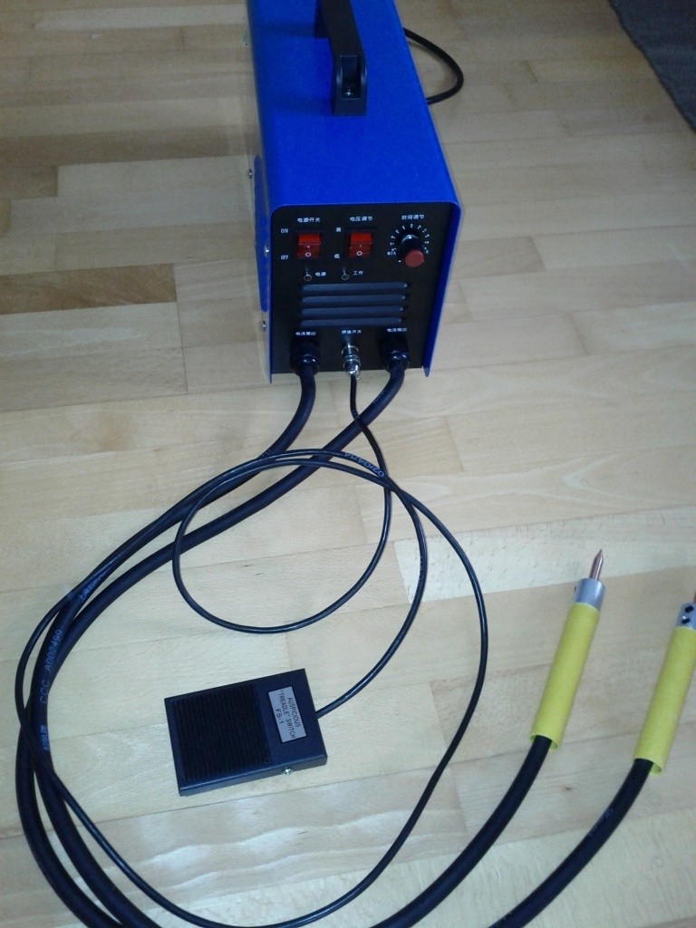
the DN-5 welder:

lcXeTq.jpg


from left to right: main power switch, foot switch on / off, pot for welding time 0-10 (i believe without steps)

yyALq9.jpg


modifications:

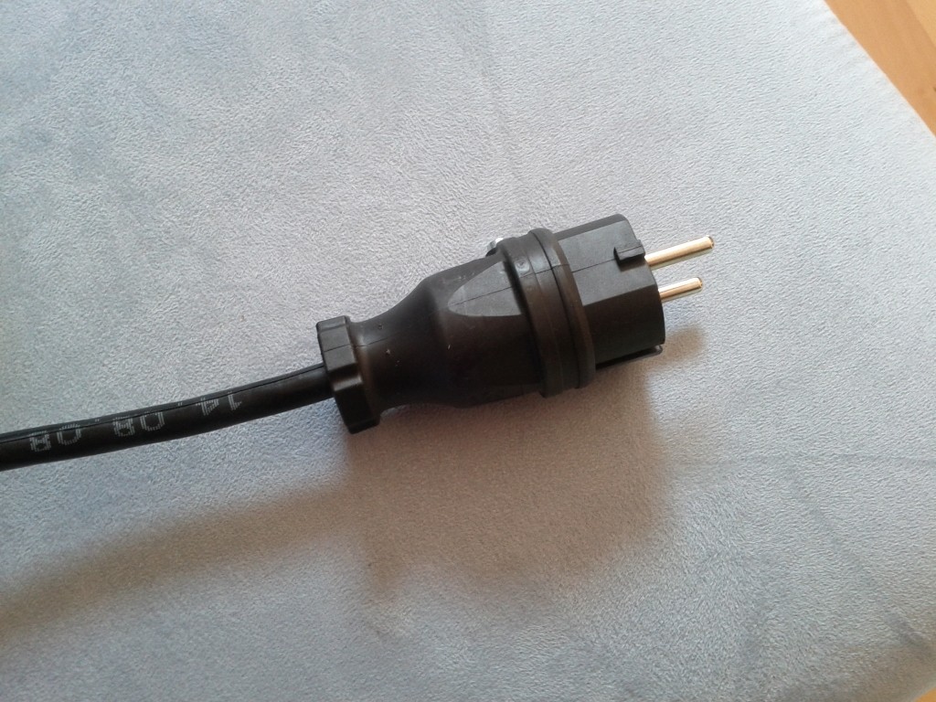
installed a solid 230V jack

xEzUDK.jpg


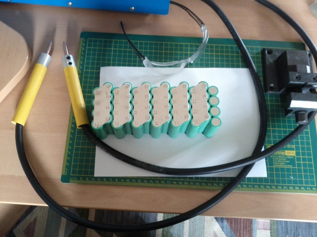
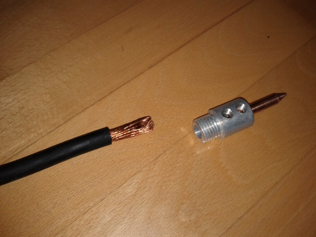
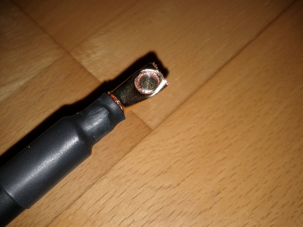
as they put the loose wire into the tips i have put a wire-end sleeve on it and shrinktube
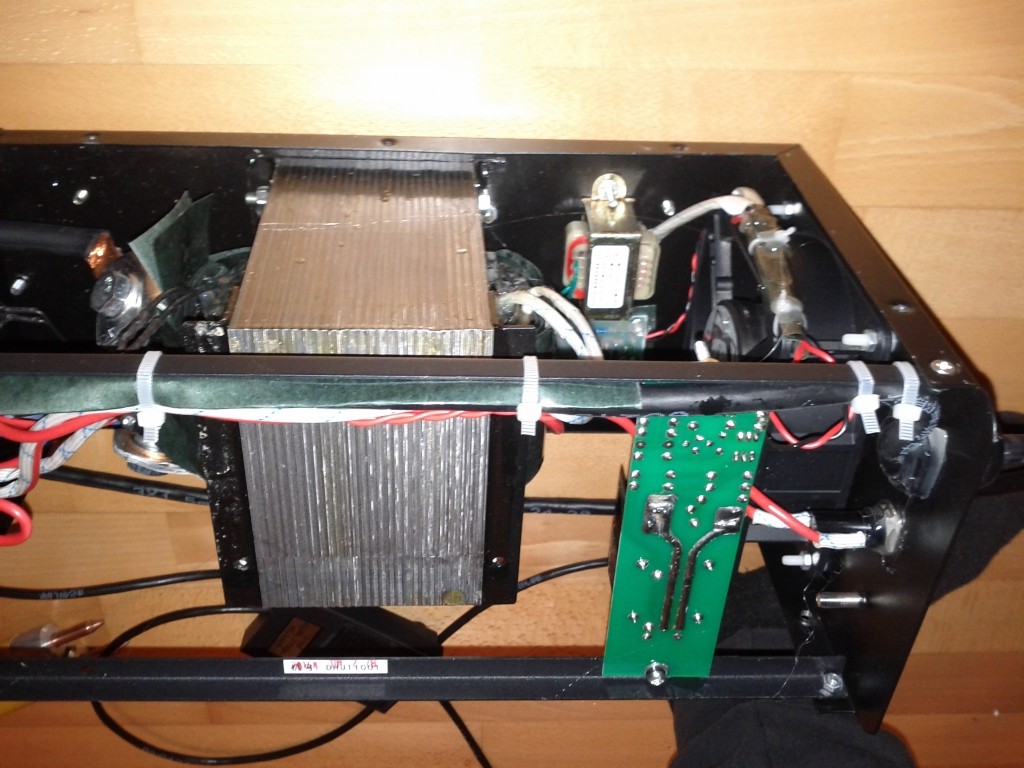
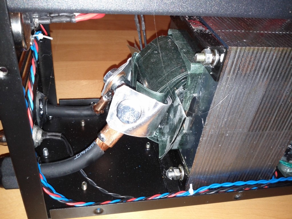
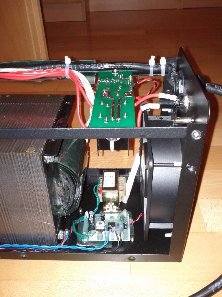
vwnBuF.jpg


1BZ0v3.jpg


thats inside:

k9B4Lm.jpg


J8UnD3.jpg


pwrPYV.jpg


1PmZeC.jpg


9h8LZ9.jpg
 
the welding results:

first i must say i had not much success welding 0,3mm pure nickel with the DN-5, but for me this did not turn out to be a problem because personally i think its to thick for 18650 cells which only have about 0,3mm wall thickness on can side.
the reason is with 0,3mm there is higher heat impact and risk of leakage. if you pull off 0,3mm material from the can (or think of vibrations during riding) it could be you tear a hole. while with thinner material the material will break first and not the cell. this is something we should think of!
as material i used pure nickel and also nickel coated steel which often is called hilumin. the results a are not exactly identical which i have described closer on the following pics.

on all pics on the left side there is the result with pure nickel and on the right with hilumin. same time setting (1,5):

KBZeJw.jpg


hilumin is a bit harder to tear off but it makes more blackish stuff around the dot and the tips. pure nickel gives a cleaner weld and keeps the tips clearner. further there are less flying sparks.
electric conductivity is identical on both materials which is about 5 times less then copper. hilumin is normally cheaper.

zu0sSC.jpg


PU0zju.jpg


DOY7ND.jpg


finished packs: always wear a safety glasses because of the sparks

TpgZZt.jpg


FxxIv3.jpg


2sTay9.jpg
 
Allex said:
Thx for this!
Have you tried to weld with 0,3 nickel, just to see if it can take it?

yes i have tried 0,3mm pure nickel, but the weld only did hold good at setting 4 or above. at this setting there is high heat impact (large blue area around the dot) and the welds don't look that good anymore..
i know in some cases 0,3mm would make sense, but if you have the options you can design the pack that 0,15mm is enough.

as example with 20mm x 0,15mm hilumin i get more than 30mm² cross section on 12p group which results in 6mm² copper equivalent. this is enough for such short distance and will add negligible resistance to total battery resistance.
 
thats how i build batteries:

the single p-groups i stick together with CA. the brown strips are kapton band which doesn't melt until 200°C or above so this is a protection against short circuit caused by to much heat and also it should protect against chafing
but as the pack is all glued together i guess there will not be much chafing.

Hroayf.jpg


the s-groups i stick together by adding hot glue in every gap. its better if you have a second person for help by this work because you want to have a even surface without glue bumps.
one adds the hot glue into the gaps while the other licks the finger and press the unwanted but unavoidable remains flat :lol:

6pv4U8.jpg
 
dbaker said:
Do you think the DN 2.5 would be sufficient for .15mm nickel?

i cannot give you an answer but i would not buy it. with the DN-5 or DN-10 you are on the safe side.
 
How much pressure are you using with the electrodes when spot welding?

Does anyone know where to find those strips/sheets that makita uses for powertool packs. Those are plated copper, not nickel. I just dont know are they tinned copper, nickel plated copper or something else? But very easy to spotweld and much better conductivity compared to pure nickel.
 
I am tempted to order one of these , but damn shipping is a killer.

Also on tht cart100 if you go with the default weight it provides it is 3000g which is 3kg.

So id assume after you order they come back and say you need to pay 200$+ more in shipping.

So if one was to order from there id think you should list 20000 grams which changes the shipping from 70$ US to 313$ US. OUCH

Does that all sound correct ? Basing the 20kg on madin88's first post.

Nice thread btw thanks.
 
You can also check the shipping with this seller:
http://tw.taobao.com/item/15904562609.htm?spm=a1z3p.7664257.2014080704.2.fl3JZ4

But you will need to translate the page :)
 
Very interesting to see the insides of the DN-5, thanks for the info. I believe the biggest reason you're not getting the greatest results with the thicker nickel is the nature of a transformer based spot welder VS capacitor discharge or one powered by high pulse capable batteries like large starter motors or even lipo. Because maximum current is inherently limited by the wall supply current and vdrop, the duration of pulse must be much longer to get required heat/penetration leading to the heat related discolouration and potential for internal damage. My battery setup will pulse into kilo amp range.

With suitable fets and a capable power source (in my case 130ah of commercial starter batteries) I'm achieving excellent adhesion on 0.3mm pure nickel with <10ms pulse times. The nature of the materials means that although the can of the battery is thin (though definitely NOT 0.3mm, it is thicker than that) it's much stronger than the nickel material and thus the nickel gives way before the wall of the cell does. This can physically distort the can, pulling on the spot weld but I have not been able to get one to compromise its seal and I was VERY rough with lots of testing on junk cells. I do not believe vibration will cause spot welds to pull out if the battery is suitably assembled like what you're doing with the hot glue, after full gluing and welding my battery is very dense and has zero potential movement.
 
Ohbse said:
The nature of the materials means that although the can of the battery is thin (though definitely NOT 0.3mm, it is thicker than that) .

Here is one of my LG DBHE II cells :)
http://endless-sphere.com/forums/viewtopic.php?f=14&t=57291&start=425#p1011357
file.php
 
cwah said:
Are you sure tape is enough to protect against chaffing? The tape may wear out after 6 months

i believe there is almost no chafing between the cells, but its better than nothing ;) the main reason i used kapton is to have protection against a short between the s-groups if one cell fails and gets too hot so the shrink tube melts.
must say i only do this on batteries for highest power densitiy because its very time consuming.

anttipaa said:
How much pressure are you using with the electrodes when spot welding?

Does anyone know where to find those strips/sheets that makita uses for powertool packs. Those are plated copper, not nickel. I just dont know are they tinned copper, nickel plated copper or something else? But very easy to spotweld and much better conductivity compared to pure nickel.

not sure how much pressure i add, but not too little.
do you have link to those copper tabs?
i have seen some with nickel-copper alloy, but from what i have found out it has not much better electric conductivity than pure nickel or hilumin (i think about only 20% more), and im not sure how good it can be welded. probably i will give them a try.
these are the tabs:
http://www.amazon.de/Lötfahnen-Schw...=UTF8&qid=1426928654&sr=1-1&keywords=lötfahne

@ Ohbse

yes you have right. a short time and high current is what makes a good weld. i cannot tell you how a transformer welder compares to a capacitor or battery type welder, but the peaks are definitely in the kW range DN-5 = 5kW peaks!!
also the tips and the fat 35mm² wire itself gets hot. i need to stop after 100 welds because it was too hot to touch!
 
madin88-

What a fantastic thread!

Great photos, great advice.

Here come the noob questions, though:

How does the "wire sleeve" on the end of the cable connect to the silver colored piece and the base of the electrode? I see the silver colored piece has a few threaded holes, but the wire sleeve doesn't look like it will fit in them. A photo would be nice.

Second, the kapton tape, is it a cylinder that surrounds the cell entirely or just strips running up and down it? Again, a photo of the kapton tape and the process of putting it on would be nice. Why is it so much work?

Do you think it would be a good idea to make a similar welder, but replace the very heavy transformer with large capacitors and pay for them with the savings in shipping to Europe or the USA?

I'm planning a pack with 18650s and sheets of nickel as you show in your photos, so I am shopping for a welder.
 
You know that your battery will be on a bike, and that your whole battery will be subject to vibration.

The only thing absorbing vibration is the layer of glue between the cells. And with the weight of the battery and vibration over time some of the glue may weaken.

Then you start to have chafing, and then the layer of tape and cell heatshrink start to wear down....

Between 2 strings of cells you have a difference of potential, so risk of short.

that's why I am using plastic cells brackets although it makes it bigger because of the inherent risk with bicycle riding. I think you need at least another layer of protection between each string of cells
 
cwah said:
You know that your battery will be on a bike, and that your whole battery will be subject to vibration.

The only thing absorbing vibration is the layer of glue between the cells. And with the weight of the battery and vibration over time some of the glue may weaken.

Then you start to have chafing, and then the layer of tape and cell heatshrink start to wear down....

Between 2 strings of cells you have a difference of potential, so risk of short.

that's why I am using plastic cells brackets although it makes it bigger because of the inherent risk with bicycle riding. I think you need at least another layer of protection between each string of cells

Vibration can be absorbed later with pad. Nickel strips also are connecting and attaching the cells. With some pad between the battery pack, vibrations can't break the glue layers if they are reasonably enough and all the faces of the cells are glued. Cell brackets absorb almost nothing because the plastic material and forced the vibrations to hit the nickel strips.

Glue is to much better absorbing shock and more than enough to absorb vibrations if the pack is right wrapped.

This is an example of a relatively big pack 195 cells. And that's how I solve the vibrations issue from the outside. 10mm of insulation cushion.

In my case the battery is mounted on a rigid frame, so the battery take the vibrations raw. I can feel how the cushion do its job, and the battery doesn't hurt so far. If any of the cells if ripped apart someday I will feedback that for sure.

DSC_0265E.jpg
 
silentflight said:
How does the "wire sleeve" on the end of the cable connect to the silver colored piece and the base of the electrode? I see the silver colored piece has a few threaded holes, but the wire sleeve doesn't look like it will fit in them. A photo would be nice.

Second, the kapton tape, is it a cylinder that surrounds the cell entirely or just strips running up and down it? Again, a photo of the kapton tape and the process of putting it on would be nice. Why is it so much work?

Do you think it would be a good idea to make a similar welder, but replace the very heavy transformer with large capacitors and pay for them with the savings in shipping to Europe or the USA?

its noting special how the wire is fixed. the silver part is aluminum. one bolt secures the copper tip and the other bolt the wire. the yellow grip is screwed to the aluminum part.

the kapton tape does not surround the entire cell. only strips so there is some area left for the hotglue like you can see on the pics. its so much work because i had to cut 2 strips per cell which makes about 480on this pack.
the thickness of kapton is about twice of tesafillm.

afaik you cannot swap the transformer for caps or battery, because the FET's are only made for low current and 230V AC power. you also would have to change this circuit so its about the same as you build a complete welder.
 
Back
Top