MEBO battery charger 48V 5A - can I adjust voltage?

meelis11

100 W
Joined
Jul 30, 2013
Messages
116
Location
Tallinn, Estonia
Hi,
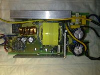
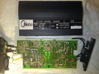
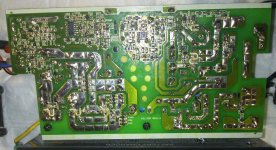
I opened it up and cannot see potentiometers anywhere. Same 5A charger is available 54.6V (mine), 58v, 36V etc.
I thought that I just open it up and can make little adjustments - I have 12S lipo but charger is for 13S (my future battery)

Any idea is it adjustable charger?
Some pics here about inside are included.

thanks,
Meelis
 

Attachments

  • DSC_3194.jpg
    DSC_3194.jpg
    114.8 KB · Views: 623
  • DSC_3195.jpg
    DSC_3195.jpg
    156.2 KB · Views: 1,071
the output voltage is controlled by the feedback network of those small surface mount resistors attached to the cathode of the opto transistor that spans the slot over on the top side in your picture.

i could make out R13 where i think the resistor divider bridge between ground and the output voltage is located. you would need to change those SMT resistors or add a trimpot to adjust it in one direction or the other.
 
Hi,
I posted one extra photo with PCB and better resolution.
Do you mean where R9 R10 are (bottom right)? I cannot see R13 from this picture, or is is on other side?
 

Attachments

  • DSC_3196 (1).jpg
    DSC_3196 (1).jpg
    226.4 KB · Views: 1,055
you can see the slot at the top that the optotransistor spans from back end to front end of the charger. R26 printed next to the slot.

the traces from the cathode of the opto run down to where there is R13 printed clearly on the pcb. those SMT resistors are the divider bridge that provide the feedback to control the optotransistor which is how the output voltage and power is regulated.
 
Thanks, I will need to open charger to take closer look!
R13 and other resistor next to it then make voltage divider? If I replace these resistors with multiturn potentiometer (10K?) then I should have adjustable voltage? :)
 
you would not replace them but you would add a trimpot on one side of the divider or the other to allow you to decrease the resistance in a controlled manner so that the voltage feedback to the cathode of the optotransistor allows the voltage on the output to be higher when your feedback voltage is the same.

when you add the trimpot in parallel the equavalent resistance decreases for that section of the divider.
 
Back
Top