LiPo Repack question.. restructure or adding extra cells?

DrInnovation

100 W
Joined
Jul 28, 2014
Messages
110
Location
Colorado Springs, CO
I am rebuilding some of my lipo packs. each pack had a cell that went bad and dragged the 3P group down below 2.7V (one to 2.3, another to 1.8 another to .85 and a 4th to .67 and 5t and 6th at .35 -- the latter three were from packs sitting on the shelf for quite a while until I thought about disassembling and rebuilding). In every pack but one, it was the bottom group of 3 Cells that had the problem (and the other had a physically broken cell connection). Is it common for the same cell to consistently die?

My bike wants 7S, and until now I've kept things as a custom 1S6P + (3S+3P)2P + (3S3P)2P where + is serial and the (3S3P)2P mean two standard thunderpower 3S3P 11.1v 20C lipo packs connected in parallel cellwise via their balance connectors as well in parallel via their power connector. I did this so I could disassemble them and continue to use my RP charger and test balance using a CellLog8, while still allowing group level parallel.

I've disassembled each group and am recovering the 2 "good" cells, which seem to be holding their charge overnight. I reassembled my first 3P cell group, first one shows an IR of 8mohm testing under a 3A load (.5C). Working my way through the other cells, first restoring to 3.8v letting them sit overnight then taking them 4.2, giving them a day then doing a discharge test and measuring IR.


Working my way through the others and I'm pretty pretty sure I'll have about 12 good cells + 12 normally used cells. I started thinking that maybe the recovered ones will be weaker (though the first IR was good, it was also the least discharged pack), and that maybe I should be rebuild the pack as 3P+3P+4P where the 4P are the recovered cells. This would help make up for any weaker discharge rate and lower capacity in the recovered cells.
(The recoverd 3P3P4P packs would be in parallel via balance leands with undamaged but used 3s3P packs.

I just ordred a BMS from SignalAB, so I figure that can help with the balance with the slightly different group size (especially if the 4P is from cells that really do have lower capacity). Am i missing something that might cause problems with this configuration?

Also if I'm going to rebuild and use a BMS, should I just scrap the idea of keeping the pack in normal configuration (I'll be down to two anyhow and not sure I'd want to fly with them given the year of use on the bike) or just rebuild all the good cells I have left into a single 7s where I spread the recovered cells out and put together as many 7P and leave the rest as 6P. This would put all the cells I have to use and might be simpler for the balance leads connection to BMS. With a BMS Is having some extra weak cells (but not shorted and reasonable IR) connected in parallel with the group a good idea, or should I just keep it with the best 42 cells I can get in the 7s6P configuration?
 
Well I've rebuilt the pack (and was able to slavage enough cells to keep 7s6P for now with some spares). I decided to keep them in normal pack mostly so I can still use the balance charger. I've started with an 18650 build (still charging/testing cells) and so may even put these back into RC usage ;)

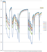
But I'm not sure how much variation I should expect in cells in normal usage. here is a Celllog of the 7s6P packs during my commute.
Screen Shot 2015-07-21 at 2.18.53 PM.png
After charging the resting voltage difference was 20 millivolts (.02 volts). But under load the max difference grows to 200milivolts (.2volts) from the worst and 100milli volts below the next weakest cell. However they all recovers at rest back to 20-30 millvolts max difference. This makes it clear that Group 7 (which is really a 6P group of 2200 mah 20C lipo cells) is weaker than the rest.

What I just don't have enough experience to resolve is if that is enough weaker to worry about it trying to do something about it now (before it takes more damage) or if i should just watch and see. Should I be proactive and add a 1-3 more 2200mah 20C cells to group 7. Is the difference to group 3 (the second weakest) enough to address it now and maybe 1-2 more cells into group 3 which is the second weakest. It is a bit of a pain to disassble and resolder packs but if it will actually improve life to do so then might as well do it now.


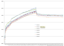
And just for fun, I thought check that the SingalAB BMS charging this pack to check the BMS high-voltage cutoff and bleeding was working.. so I cranked the meanwell up to 30V and sat and watched it. here are the celllog of the final bit of the charge):
Screen Shot 2015-07-21 at 2.51.13 PM.png
Sure enough the BMS kicked off the charger and then bled down the overvoltage groups to within .02 volts. It did not seem to restart charging needed to recover the lowest cell but maybe .02 tolerance is within the spec?

For now I guess .02 V is close enough to balanced so I'm happy with the way the BMS works. Not sure if I left it plugged in overnight if it might get closer but I did not want to try that just yet. I won't normally charge this high but good to know that if I need to rebalance (which I was doing every week lately), I can just charge it up.

Can also see that group 7, the weakest cells in the high load condition, are the first ones to hit max voltage. Again making me think i could toss some cells in that group to help them out, but I don't know the advantage of "unbalanced" in number of cells vs unbalanced in capacity. Any comments?


I can
 
i assume you have a lipo signalab BMS. in almost all lipo BMS, the charging shuts off when you exceed the 4.25V threshold for HVC.

the charging mosfet will not turn back on until the voltage has dropped down to 4.05-4.08V.

your group 7 has high resistance cells in it so it is resistant to charging so it never reaches the same level of charge as the others so it has higher internal resistance because it is always at a lower SOC than the others. that is why the voltage sags so much on discharge.

this looks like something you would get if you just randomly found laptop cans and built a battery from them.
 
I've seen worse than 200mV difference under load but its certainly worth keeping a close nose/eye on. Have you tried doing IR calculations from the celllog data correlating to loaded Amps?

Sometimes, I make a mental note of max battery Amps while doing a short log. Later on, do the math of cell voltage sag and noted current to calculate IR. Good thing to know for comparison over time.
 
dnmun said:
i assume you have a lipo signalab BMS. in almost all lipo BMS, the charging shuts off when you exceed the 4.25V threshold for HVC.
Yes lipo signalab BMS..

dnmun said:
the charging mosfet will not turn back on until the voltage has dropped down to 4.05-4.08V.
Do you mean the cell voltage has to drop to 4.05 or in the input charger? (I'm using a meanwell to charge, so it won't be dropping input voltage unless I unplug it). Just charging until one cell hits 4.25 for the high cell and bleed it down to 4.2 will not ever bring the runt up from 4.18. Even if I unplug and replug the top cell will go from 4.2 to 4.25 much faster, but maybe the other will catchup a little. Might need many many cycles, so is the BMS expecting the charger to keep dropping on/off?


dnmun said:
your group 7 has high resistance cells in it so it is resistant to charging so it never reaches the same level of charge as the others so it has higher internal resistance because it is always at a lower SOC than the others. that is why the voltage sags so much on discharge.

this looks like something you would get if you just randomly found laptop cans and built a battery from them.

It does reach the same voltage, in fast it is first to the HVC, but even after 25 mins of rest and BMS bleading, it was the highest voltage. I understand that absolute capacity might depends on more than just voltage, but how does level of charge get impacted?

These are all thunder power 20C lipos, not 18650s. But they are old (2007/2008) and well over 300 cycles, some may have over 400. On most of the cycles the were used at 3C-5C and maybe 100 cycles were using 5-10C.


The more important question what is the best thing for me to do with it. Should I be trying to identify the high IR cell and get rid of it, or just adding more cells to that group?

Thanks
 
if the cell has high resistance to charging then the voltage expressed at the terminals during charging is higher than a cell with a lower resistance to charging even though the cell with the higher voltage is not charged to the same level.

so the 7th channel starts out with lower SOC and has higher resistance already along with the increased resistance because of the lower SOC so that is why the voltage sags so much more in your graph.
 
Ykick said:
I've seen worse than 200mV difference under load but its certainly worth keeping a close nose/eye on. Have you tried doing IR calculations from the celllog data correlating to loaded Amps?

Sometimes, I make a mental note of max battery Amps while doing a short log. Later on, do the math of cell voltage sag and noted current to calculate IR. Good thing to know for comparison over time.

Interesting idea though I don't have an watt or amp meter on the bike. I guess I could do a test run with my multi-meter in line to get a max. The 8% grade is right out the door so I could jury-rig it up inline for a quick ride.
 
I tried to measure while riding but my multi meter maxes out at 20A.. at hit that starting out on the flats.

dnmun said:
you should be able to see it when you charge.

Not sure what you mean by "see it" are you saying to measure the charging current, which I guess I can and use it to estimate the pack IR. I would agree the pack has greater IR, can tell that without measuring the current (which is probably about 25 or 30A given its a 600watt motor maxed out. )

I'll check charging current and resulting voltage changes tomorrow.

I know how to measure IR give load and voltage Drop.. is measuring IR on charging similar just considering the "charge current" as the load?


I would agree the pack has higher IR, maybe the more important question is what to do about it. Should I disasseble the 6P and try to remove it, or just add a few more cells (less work)?
 
unless you have the correct tools the internal resistance is not possible to measure. measured at 1kHz on a fully charged cell.

the number you think is internal resistance is a derived value based on the voltage sag from increasing the current.

the resistance to movement of the ions through the cell is what we measure as internal resistance and that resistance to motion of the ions through the electrolyte is identical in charging as it is in discharging.

so your graph during charging will show the group 7 with higher expressed potential than the other groups so you can compare them that way.

when you build a battery from used cells you have to select them by using comparable numbers for the voltage sag when you are discharging them to evaluate the capacity of each cell initially in the build process.

i do this myself when building a battery by placing all of the cells in series and discharging them into a dummy load so i can measure the capacity of each cell in the series.

during this discharge i measure the voltage of each cell constantly comparing the values to each other for most of the discharge so i can group the individual cells in such a way that the average Ri derived this way summed for all of the pouches in parallel is the same for each of the cells in the series that make up the battery. so then each cell has about the same voltage sag as the others so the battery is relatively balanced for Ri and capacity on each channel.
 
If you can find something else to apply a sub 20A load (old AC heater element?) as long as it’s around 1C you’ll see decent results. 1500W AC heater from an oven/range pulls around 5-7A from my 60V’ish battery packs. Good enough for 5Ah cells/groups IMO.

It’s mainly for comparison to each cell in the string rather than attempting to create standardized IR (impedance) test data. Yes, apply same Ohm’s law in reverse for charging if that’s any easier for you?

Practical IR numbers - I found to be good comparison records for historical cell health information. Over time, if a cell begins to change drastically for the worse, there’s usually an obvious line which can be drawn to help visualize and better judge when to pull the plug, so to speak.

You’re paying careful attention and thinking about the situation(s) so I wouldn’t expect anything to get out of hand. Of course, always use all your senses - sight, smell, touch and brain to better qualify if any cells have become compromised.
 
Did a static DC Internal Resistance computation (i.e. ignoring frequence issues) which is easy enough I can keep doing it once a week if has enough diagnostic value.

With no charger group 7=3.995v and with charger providing 7.7Amps group 7 = 4.098v so .103/7.7 = 13.4milliohms.
For each of the 7 groups the static IR is 6.8 8.1 12.5 8.6 7.9 7.8 13.4 respectively.


So look like both group 3 and group 7 have noticeably higher IR, which is of course, consistent with the discharge plots from the cell logs.
but IIRC 12-13 mohms is still in the range of usable for RC lipos.
 
do you have a way to disconnect all the cans so you can charge them all up to the same full charge voltage in parallel?

if you charge them all up to full charge and connect them in series then when you discharge into a dummy load through the wattmeter to record capacity you can monitor the cell voltage of each can in the series.

you have the recording cellog so you could rig up a sense wire type of JST plug with alligator clips on each sense wire to each can in the series and that would give you a recorded view of the comparable voltage sag of all the cans.

then go through and remove all of them that have high internal resistance (or large sag) and then mix and match the remainder so that each channel has the same average internal resistance which in this case would be just the recorded voltage values from the cellog.

that would give you the best chance of having a pack that is 'balanced' or equivalent in capacity and internal resistance on each channel.
 
I give up on RC Lipo for my bike motor around 20mOhm/cell.
 
Dunum and yKiick.

Thanks.. these are lipo soft packs that are spot-welded or soldered at the aluminum tabs, so a pain to disassamble/reassemble compared to 18650s and increases damage to the cells from heating with soldering iron when reassembling. For now I think I'll wait and watch. After 10 miles the pack is down to 3.8v per group and max voltage differential is 28mv (it was 20v difference after charging).
 
Totally agree with you about reworking those type cells. I also don’t see anything too alarming about your cell IR.

Would it be nice if IR grouped a little tighter? Sure, but I’ve used packs with similar differences for years and it was never a practical problem for a bike pack.

The main thing is to catch if/when any cell IR drastically changes and you lose so much charge energy to heat that the imbalance creates unstable over discharge condition.

I would strongly recommend some type of power meter. Watts up, Turnigy, GT Power, CA (cycle analyst). If even just temporarily.

Use one of those for a while and then you’ll know your max battery amps well enough to calculate IR with only the CellLog 8S ride logs.
 
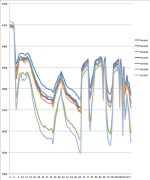
Its been about a year since i posted here and got some useful feedback. Just did another full checkup and I figured its time for an update incase anyone has similar issues and wonders what was the outcome. I took ykick's advice and decided to just watch it -- saving me from a lot of work rebuilding and/or money in buying new. After 11 months and probably 200 commutes on it my discharge, the spread under load is similar and still reasonable:
Screen Shot 2016-05-29 at 7.30.19 AM.png
This is to work, 1.6miles up 500 ft, with sections of 10% and 8% grade. (The curve differences are starting lower and time spreading as it depends on where I have to stop/wait for traffic).

I've been charging to only 4.1 rather than 4.2 to improve longevity and since my commute does not need the added power. When I take longer trips I adjust the meanwell and charge to 4.2 but that is once or twice a month.

I did go out and get a CellMeter7 so I could more easily monitor IR and more easily manually balance. (While I have added a BMS for protection, it top balances and its more of a pain since I used a Meanwell to charge and it does not start/stop its current so when BMS cuts off it simply stops charging to balance I would have to manually plug/unplug to get the next round of balance). The CellMeter helps with balancing and I toss it on every few weeks when the spread gets above .05v. I have manually bled down the weakest cell(7) one time when had gone more almost 2 months without balance the spread grew to about .1 and I wanted to disassemble anyhow to physically check the pack).

Using cell meter, IR on Cell 7 has increased to .20ohms, it was .17 on the same device last august , so only a .03 increase over the year -- is that reasonable? (the .13 below was a manual estimation in july)
Ykick said he retires LiPo at .2 so I'll start watching more closely, but for now I'll just keep watching.
 
Back
Top