8S2P 24v Battery – Help needed.

AJM

1 mW
Joined
Feb 17, 2015
Messages
18
Hello all,
Just wanted to introduce myself and explain my reason for registering here.
I live in Canada and am a cave diver, have been for many years and what brings me to your wonderful site is a project I am working on that could use a bit of input from an electrically educated group.
I have used the search function but do not find any clear answers to my questions.

So I hope you too will find my project of interest and help me with a few points of information.

I am looking to replace my SLA battery's in my DPV (Diver Propulsion Vehicle) “Underwater scooter”
with LiFePO4 cells for longer run times, higher cycle life. We are finding we cannot get enough range from our 24v - 18ah SLA's and I want to move up to a 24v 30ah Lithium pack.
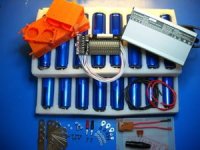
I am planning on using Headway 40152S cells in a 4 x4 - 8S2P arrangement, with a Signalab V5 BMS.

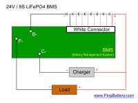
The reason I am posting here now is to ask if someone can confirm my wiring configuration of the pack. I have attached drawings of how I think it needs to be wired to achieve the desired voltage/amperage and want to know if I am on the right track before continuing with the project.
(I am only in the fact gathering stage, and not building at the moment)
Any help would be greatly appreciated as well as any other pertinent information about building a battery of this type.

Thank you,
AJM


EDIT: I am unable to attach my diagrams for some reason, if able to assist PLEASE contact me and I will send the diagrams to you.
 
I did try to upload attachment through the "Img" function - did not work it is asking for a URL?
Will try again.

Thanks,
 
hi,

Upload attachment is at the bottom of the edit box. so

1. click upload attachment
2. choose file
3. add the file
4. submit

you should have the image.
 

Attachments

  • upload_attachment.JPG
    upload_attachment.JPG
    29.4 KB · Views: 3,381
you will only need 12AWG for the serial connections and 26AWG for the parallel connections.

at the BMS, bring both of the 12AWG to the B- spot on the BMS. if there is a separate sense wire for B0 then you will need to run a wire from B- to B0 on the BMS.

on the output, you can run two 12AWG to the controller and tie them together there. you do not need paralleling connections for the terminal B- and B+ spots since they are tied together in the current collector. but you need a sense wire from the top B+ spot on the pack to the B8 on the BMS.

post up a picture of your BMS closeup so we can see it.
 
Here is the kit I was planning on going with,I will be using the connector plates and cell holders as a square block so I will not need wire except for the +/- connections and BMS connections.
I will be using the BMS I added above not the one from the kit. (diag of wiring added below)

I have also read that it is not optimal to have both pos. and neg. wires coming out of the same side of the battery?
And If I am understanding correctly so far , it seems that my "wiring" diagram of the 4x4 - 8S2P config is correct, any tips (do's/dont's) on the construction.

- I am planning on individual charging of the cells before const. and have ordered 4 small chargers
- I am reading up on cell matching, but am limited by a small amount of cells (16)
- I have ordered a 6 amp charger for the pack (do not need fast charges)
- Plan on wearing gloves with an insulated work mat, insulated tools...etc.
- Have Watts up meters and Eagle Tree date logger to monitor pack and scooter performance.
- Have a 300 ohm burn tester (16 amps) to mimic scooter draw for the SLA batteries burn testing (need run times for cave diving), can I use it on this Lithium pack?
Again, thanks for the input, really appreciated.


Thanks,
 

Attachments

  • Headway kit.jpg
    Headway kit.jpg
    18.7 KB · Views: 3,383
  • 8s BMS Wiring.jpg
    8s BMS Wiring.jpg
    108.9 KB · Views: 3,383
you do not have to match the cells and if you just connect all of the cans together in parallel with a wire under the screw head then they will all be balanced to start off with. no need to charge them separately since the BMS will balance them when you finally charge them up the first time as a pack.

working on individual cells is not worth the effort if they are part of the same manufacturing lot. they are already within a few % of being balanced coming off the formation charge in their current state. they will have almost identical capacity also so no need to test capacity which you cannot until they have had several cycles to mature anyway.

if you have a wattmeter then after you have built the pack and cycled it several times to stabilize the surfaces then you can discharge it into a dummy load through the wattmeter to get a good idea of capacity and how long it will run. the cold will have an effect also, just as it was with SLA.
 
Hello all,
Thanks for the comments so far.
I have constructed the battery pack and have soldered the wires to the BMS, so far so good.
I am now ready to connect the BMS to the battery but before I start connecting the sensing wires, I do have a few more questions.

1- Can I add all the wires to the battery and then plug the connector into the BMS, or do I plug in the connector to the BMS first and do the wiring to the battery second ?

2- If it gets plugged into the BMS first before wiring it to the battery, do I start with the Negative wire side of the plug and connect all leaving the Positive wire to the end or do I start at the Positive wire and work to the Negative wire last ?

3- When completed and I begin to "cycle" the battery, how much should I draw out of the battery before charging and repeating the process, how many times should I cycle it before it is considered at full capacity ? (I do understand that there isn't a fixed number, but on average ..how many times ? )

Again I welcome any additional comments besides the questions above and have included the BMS wiring diagram below for reference.

Thank you,
Anthony

ping bms.jpg
 
solder the sense wires to the battery first. then use you voltmeter and walk the meter up the entire series of contacts in the plug to verify they are soldered in sequence and the voltage jumps the same direction for each pin in the plug.

if they are in sequence you can plug it into the BMS.
 
dnmun said:
solder the sense wires to the battery first. then use you voltmeter and walk the meter up the entire series of contacts in the plug to verify they are soldered in sequence and the voltage jumps the same direction for each pin in the plug.

if they are in sequence you can plug it into the BMS.

dnmun,
Thanks for all you help.
I have connected the sense wires I believe as you have described above, before I plug it into the BMS would you, or anyone with experience doing this be kind enough to confirm my wiring is correct ? I really don't want to leak all the secret smoke. ( a phrase we use, to describe incorrectly wired parts) I am a Heavy Duty mechanic by trade.
Below is a picture of the BMS wiring diagram, I have added the voltages I have measured at each terminal in the plug to the diag.

As always...Thank you,

V5 BMS.jpg
 
Thanks,
I measured the black wire with the black probe on "B -" and get no voltage reading, the first reading of 3.4 is on the first white sense wire?
Isn't that black wire and "B -" going " ground to ground" for a reading of zero?
 
no. on the ping signalab sense wire cable there is the same number of wires as there are cells in the pack. so a 16S pack has 16 sense wires and the black wire is #1.

that black wire goes to the top of #1 and the bottom of #1 is the B-, so between B- and that black wire you should find your 3.6V.

except be sure the B- is soldered to the bottom of the pack already.without the connection of the negative terminal of the battery to the B- spot on the BMS you will have an open circuit when measuring between B- on the BMS and the sense wire on the top of #1.
 
dnmun, again many thanks.

Your explanation above really helped, I now have the BMS connected correctly with the proper readings ascending from the black wire to the red.
I have put it on charge to top up and balance, I have also begun to cycle it with a few shallow draws with my burn tester - down to 25.2v and charged it up again 3x.

One thing I have noticed is that the third L.E.D on the BMS has never lit up, not once through the initial charge and balancing, all others were blinking on and off as it balanced, then went to solid red. The third one didn't even come on at all when they all went solid red. And have not seen it come on once during the cycle charges? I have left the battery on the charger for 24 hours before the third burn test, still have not seen that third (from black wire) L.E.D come on...do you think this is a sign of an issue I should be investigating. it measured 10.3 v at the plug when I was checking for the correct ascending voltages before plugging it in.

Hmmmm??

Anthony
 
do you have a voltmeter? can you measure the individual cell voltages, to .01V on your DVM and post them here? measure the voltage across the resistor for that #3 channel too. do all of this while the battery is charging.
 
I measured across all the resistors, will need to remove the battery from its mount to access the cells to measure those (will post when this is done)
On the resistors, I get these numbers while charging, I checked 3 times during the charge.
If I am doing this correctly I found.

Running from black wire side to red ( 2 minutes between tests)
First test - .01, 3.07, 6.10, 9.16, 12.18, 15.23, 18.35, 21.40
Second - .01, 3.08, 6.16, 9.22, 12.31, 15.40, 18.39, 21.62
Third - .01, 3.08, 6.17, 9.25, 12.37, 15.46, 18.56, 21.74

Watched BMS until charger cut off (28.7 v), 3 L.E.D's briefly lit up then went off.
Charger cuts back in for 5 seconds(at 27.95) v, 1 L.E.D lit up.
Charger keeps cutting in/out for 10 secs max, no L.E.D's light up at all. (charges 27.95 – 28.60)

I assumed with this BMS, that as each cell reaches full – that L.E.D would light up and stay on.
And when all L.E.D's are on constant – that means that all the cells are “balanced” and of equal voltage.
I am finding them all off and the charger has stopped charging, until the battery voltage drops back down to below 27 volts and the charger cuts in for 20 seconds then turns off – it does this repeatedly.

Over the past few days it has been on the charger a few times (bought with BMS from Ping) for a total of about 40 hours, I have also done a few shallow burn tests during this period.
Here is a picture of where I was measuring.

BMS check.jpg
 
your meter is not accurate because the numbers do not add up.

you wanna measure between B0 and B1, B1 and B2 and B2 and B3... for all 8 cells. if the led turns on your meter should read 3.60V or more.
 
I would agree with the inaccurate meter.
Will get a new one, redo the tests as you describe

Thx,
 
you do not have to get a new one. you may be able to adjust that one. there is a trimpot inside usually. but the turn on voltage of the leds will be exactly 3.60V so that will give you a reference voltage to work from.

take a picture of the front side and i will show you where to measure across the shunt resistor but if it climbed up to almost 3.60V already i do not think the shunt transistor is shorted.
 
I opened the DVM and adjusted it, and believe it is reading correctly, checked against my Eagle tree data logger and smart charger with digital readout they all measure the same voltage on the same battery.
Have the battery back on charge and measured at the B0-B1, B1-B2 etc as you had mentioned. They are still not up to 3.60 and will confirm the DVM when it does reach that voltage but think I see a problem already.
Battery at 28.65 and on/off charging, these reading were taken while charger on but not actively charging hard ( trickle charge).
B0-B1 = 3.506
B1-B2 = 3.591
B2-B3 = 3.936
B3-B4 = 3.578
B4-B5 = 3.576
B5-B6 = 3.570
B6-B7 = 3.586
B7-B8 = 3.596

Trying to get a picture of the front as you had also mentioned, and will post when I get one that shows well (big heat sink covers 90% of top)

Thanks,
Anthony
 
you can connect a light bulb or power resistor across the terminals of the cell with 3.96V and drain the voltage down to you lowest voltage which is 3.5V

after you drain the charge down then you can charge it up with the bulk charger to make it balance under the BMS.

use alligator clips on the ends of jumper wires, or you can buy them at harbor freight. or just hold the wire on with your fingers but be careful to not short it or leave it where it can short while you do this, like if it falls on the floor. no loose metal around to fall on in particular is important around batteries.
 
dnmun said:
take a picture of the front side and i will show you where to measure across the shunt resistor but if it climbed up to almost 3.60V already i do not think the shunt transistor is shorted.

Here is a picture with the heat sink off


BMS with heat sink off.jpg
 
Back
Top