Ultra power dense charger project.

Farfle

100 kW
Joined
Jun 27, 2010
Messages
1,759
Location
Redmond OR
Heya all, Under the advice and guidance from some very bright folks, I am starting a charger project. This will mostly be for E-motorcycle and car sized things, but the topology should work for anything.

First off, this is a "big boy rules" charger that is for those who know what they are getting into. Mainly because it is not line isolated, so any love from a grounded outlet plate while touching a non-battery isolated EV will be a painful (but most likely non-fatal) experience.

First off, how this charger differs from "normal" chargers:

Most normal chargers are laid out with a flyback based boosting PFC input stage that feeds into a bucking output stage thru a transformer. They take power from the wall very cleanly, and deliver clean, isolated and ripple free power to the battery.

Here is the layout of the important (heat and cost) producing parts in a "normal" charger:

Rectification stage -> Input caps-> Boosting flyback transistor -> flyback transformer -> Bucking output transistor -> Bucking output inductor -> Output caps.

The problem with this existing design, is that the flyback based PFC stage gets large and expensive to create high currents with, and you still need a second stage to buck the voltage back down to battery level.

Another problem with existing designs, is their obsession with creating smooth output power, this costs money, complexity and power density. It is my understanding that lithium cells are not affected by even large ripple currents (and a resident battery expert has even stated that some ripple current is actually better)

That all being said, this is the configuration of the "heat and cost" parts in the charger I want to build:

Rectification stage->Bucking output transistor -> Bucking output inductor

As you can see, this charger does away with a large amount of the "normal charger" parts, and It suffers some penalties because of it, including:

1. Poor PFC at higher relative output to input voltages
2. Cannot charge a battery that is higher voltage than the rectified AC wave peak voltage.
3. No output isolation from mains input voltage.

The advantages of this design, is that there is only a rectifier, a single mosfet, one diode, and one Inductor in the current path. voltage is kept low, and that lets this take advantage of some super baller new-to-market mosfets from STMicro and CREE. These SiC based fets are ~300-700V and have very low RDSon, and very low gate capacitance. Cree's dev inverter kit is switching 50kw at 200khz, and uses an inductor the size of a fist, instead of the 10khz IGBT solution which used an inductor the size of a large melon.

Anywho, that was a large block of text. The next post will get a bit more in depth on the buck stage, and the control uController.
 
How does the efficiency come out with your simpler charger? I understand that poor power factor inherently gives you some extra losses.

Looking forward to see where you take this project.
 
Nuts&Volts said:
How does the efficiency come out with your simpler charger? I understand that poor power factor inherently gives you some extra losses.

Looking forward to see where you take this project.

It should be very good. A low resistance fet and minimal components in the current path should achieve very good efficiency. Just seat of pants math here, but a 1.5kw charger the size of a 6 fet controller case should be very reasonable. :mrgreen:
 
On to the charger in depth:

The Bucking stage of this charger is an "Upside down" buck, meaning that the switching is done on the low side. This means that an N-channel mosfet can be used (better) and retain simple gate drive circuitry.

Here is a schematic of the power stage:


The microcontroller (actually a mostly analog chip) is a unitrode part: UCC3809-2


It does cycle-by-cycle current limiting, has an integrated mosfet gate driver that can supply real current, and has a very simple current/voltage feedback loop that is easily controlled. It is also a sub $3 8 pin chip, which never hurts :D .

[strike]The tentative schematic for the proto board that pieces are on the way to do is attached as a .PDF[/strike] Schematic is buggered, ground ref for the IC is in the wrong spot.
 

Attachments

  • Printing Print Schematic.pdf
    33.9 KB · Views: 169
Perhaps look at use of motor windings as inductor?

That might need lower frequency, but since it's inductor mass you were already carrying, it's still like its light. :)
 
liveforphysics said:
Perhaps look at use of motor windings as inductor?

That might need lower frequency, but since it's inductor mass you were already carrying, it's still like its light. :)


Not sure what the controller would think was going on if weird voltages started showing up. In fact, I think it would attempt to rectify out your charge power, possibly stuffing it back into the battery... Hmmm...

The contactor would have to be closed, but i think you could pump high freq single phase AC into the motor, and the controller might be able to pick it up...
 
Be careful the MOSFETs in the sevcon are 150v rated and the peaks of 110v AC are 170v!
 
I was thinking perhaps a contactor in series with a phase lead so the controller doesn't see the voltage.
 
are you trying to tell me the 2016 Zero wont have 6.6kw charger onboard :(

you make a great point about smooth output not being needed to charge a battery. to most any modern day psu engineer, this would be a totally foreign concept. they are obsessed with perfect control and PFC
 
While I am super into the this project, I shall point out perhaps a new benchmark for power density, the eltek flat pack S 48v rectifier.

http://www.eltek.com/wip4/download_doc_647.epl?id=7975

Dimensions are 72 x 41.5 x 217mm (2.83 x 1.63 x 8.54”) and < 850 g (1.9 lbs) and will output 43.5 - 57.6v cc/cv at 1800w with a 300,000 hr mtbf for a few hundred bucks, likely less once Chinese suppliers start selling them.

NOT trying to rain on your parade here, very interested in this idea - just wanted to point out the competition :)
 
Ohbse said:
While I am super into the this project, I shall point out perhaps a new benchmark for power density, the eltek flat pack S 48v rectifier.

http://www.eltek.com/wip4/download_doc_647.epl?id=7975

Dimensions are 72 x 41.5 x 217mm (2.83 x 1.63 x 8.54”) and < 850 g (1.9 lbs) and will output 43.5 - 57.6v cc/cv at 1800w with a 300,000 hr mtbf for a few hundred bucks, likely less once Chinese suppliers start selling them.

NOT trying to rain on your parade here, very interested in this idea - just wanted to point out the competition :)


Using this straight from 'PFC' to pack topology should be capable of beating any 2-stage topology with respect to power density.

That doesn't mean it automatically will be more power dense, just that if both were optimized to the same extent, this topology should be ~2x the power density.
 
liveforphysics said:
Using this straight from 'PFC' to pack topology should be capable of beating any 2-stage topology with respect to power density.

That doesn't mean it automatically will be more power dense, just that if both were optimized to the same extent, this topology should be ~2x the power density.

That would be quite something. 2kw charger in a 500g package would be extraordinary.
 
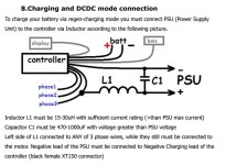
There is something really nice about the way Adaptto built their controller. They use one of the output phase as input charging current with PWM and an external non permanent inductor to make a boost converter, making it capable of charging from any power supply from 12 to the Vbat. and capable pushing serious multi kW charging power When used with a ELTEK Flatpack S 1800 48V , this make a very compact charger difficult to beat in term of dense charging solution! And it also regulate everthing CC-CV to the battery.

This highlight the fact that using the power of controller mosfet for PWM to reduce the charger topology is effective.

But i still like the old BAD BOY CHARGER solution as it keep you on adrenaline watching to not overcharge your lithium cells :twisted: it's an intense feeling that is maybe not for everyone! :lol:

Doc
 

Attachments

  • charge.jpg
    charge.jpg
    54.3 KB · Views: 3,459
This charger will do CC/CV just fine, so its not tooooo bad. Just dont sit on a wet charging ebike while touching anything grounded :mrgreen:
 
Farfle said:
This charger will do CC/CV just fine, so its not tooooo bad. Just dont sit on a wet charging ebike while touching anything grounded :mrgreen:


The same for Carbon fiber frame!!! My NYX have about 2 ohm end to end !!! lol
 
That's why AC Propulsion invented the Reductive charger.
The Reductive charger allows the easiest EV access to existing electric power infrastructure, and does so in a way that maximizes convenience for the EV user. With a Reductive charger, the EV user can plug into any existing outlet from a 110V/15A household socket to an existing EV conductive wall box, or even a 240V/80A commercial welding plug. At its maximum 18 kilowatt (kW) power rating, the Reductive charger can provide a full recharge to an AC Propulsion eBox in just two hours.

Furthermore, the Reductive charger itself saves cost. It is integrated with the vehicle drive system, so parts, size, and weight are all reduced. Over and above the battery-cost savings, the Reductive charger can take thousands of dollars out of electric vehicle cost.
Reductive charging can reduce maintenance and warranty costs
Because the reductive charger is based on an inverter, rather than a rectifier as in most other charging systems, it is inherently capable of discharging a battery pack by feeding the energy back to the utility. This capability allows a Reductive-equipped EV to perform battery pack capacity tests overnight at the customer's location, without the need to bring the vehicle in to a service location. This can dramatically reduce warranty costs, and vehicle downtime, since all battery capacities will be known prior to bringing the vehicle in for service.
 
The controller of the present invention may also be operated in a mode so as to discharge battery 12 into a power grid coupled to terminals 18a and 18b of the AC recharge port.

Pull up to an outdoor renegade and power the whole sound sys from ur bike


Patents expire
http://www.google.com/patents/US5341075
 
Doctorbass said:
There is something really nice about the way Adaptto built their controller. They use one of the output phase as input charging current with PWM and an external non permanent inductor to make a boost converter, making it capable of charging from any power supply from 12 to the Vbat.
Doc


I have some concerns about the Adaptto charging method. If I understand correctly, the output current to the battery is not constant but switching at the PWM frequency, because this is how a boost converter works. The current in one PWM state can be as high as the input current (PSU current) and 0 amp in the other state. It is if the battery internal resistance is low. Higher battery resistance can reduce the current ripple but still can be significant (e.g. instead of 10A DC the current changes between 20A and 5A at 33% duty cycle).
I don't know if it shortens the battery life... any idea?
This is the operation if it works as a simple DC/DC boost converter with the external inductor, unless they utilize the motor winding inductance somehow to generate constant current. Is there any phase current during charging?
 
peters said:
Doctorbass said:
There is something really nice about the way Adaptto built their controller. They use one of the output phase as input charging current with PWM and an external non permanent inductor to make a boost converter, making it capable of charging from any power supply from 12 to the Vbat.
Doc


I have some concerns about the Adaptto charging method. If I understand correctly, the output current to the battery is not constant but switching at the PWM frequency, because this is how a boost converter works. The current in one PWM state can be as high as the input current (PSU current) and 0 amp in the other state. It is if the battery internal resistance is low. Higher battery resistance can reduce the current ripple but still can be significant (e.g. instead of 10A DC the current changes between 20A and 5A at 33% duty cycle).
I don't know if it shortens the battery life... any idea?
This is the operation if it works as a simple DC/DC boost converter with the external inductor, unless they utilize the motor winding inductance somehow to generate constant current. Is there any phase current during charging?


Ripple current isn't a bad thing to the batteries. Think of them as massive filter capacitors.
 
This charger could up to 150Vdc pack on 110Vac and about 300Vdc pack on 220Vac. That's pretty cool.

I have a 117Vdc Leaf pack. Just using some HLG meanwells right now. I'd love to build a prototype along side you if you want to split PCB or any other costs. Just let me know
 
liveforphysics said:
Ripple current isn't a bad thing to the batteries. Think of them as massive filter capacitors.
Ok, I see. And there is the max. charge current recommendation in the battery datasheet. The peak or the average (or RMS) current should be limited to it?
If the average is set to the max then the pulses at the PWM frequency are above the recommended charge current (can be multiple of that with a low voltage-high current power supply), can't it generate some unwanted reaction inside the battery?
 
Doctorbass said:
There is something really nice about the way Adaptto built their controller.
flathill said:
That's why AC Propulsion invented the Reductive charger.
The Adaptto and AC Propulsion ideas are closely related - in both cases you’re basically running the vehicle’s existing controller/inverter in reverse, eliminating the need for a separate piece of equipment. The controller is already sized for the currents/voltages you’ll be dealing with, and its MCU brain is capable of sophisticated I-V profiles, so you already have a pretty much ideal charger right on the vehicle, might as well use it.

At the most basic power electronics level, these devices are functioning as boost converters, which is where a fundamental limitation comes in - the DC supply voltage (Adaptto) or peak AC voltage (AC Propulsion) must be lower than the battery voltage. The HV battery packs of electric cars are suited to the 340 V peaks of a 240 VAC line, but I have yet to read about an ebike pack that has a discharged voltage greater than the 170 V peak of a 120 VAC line (although I’m sure someone has done it!). So you’d need, at minimum, a transformer to bring the AC down to usable levels.

Hopefully more of the sophisticated field-oriented controllers coming on the market will start incorporating this capability, since the computing power and most of the necessary hardware is already there.
 
peters said:
liveforphysics said:
Ripple current isn't a bad thing to the batteries. Think of them as massive filter capacitors.
Ok, I see. And there is the max. charge current recommendation in the battery datasheet. The peak or the average (or RMS) current should be limited to it?
If the average is set to the max then the pulses at the PWM frequency are above the recommended charge current (can be multiple of that with a low voltage-high current power supply), can't it generate some unwanted reaction inside the battery?
Older 2013&2014 zero stuff is 1c charge rate and less with a cold battery. Not sure about 2015 or any of the other cells they have used.
 
Arlo1 said:
Older 2013&2014 zero stuff is 1c charge rate and less with a cold battery. Not sure about 2015 or any of the other cells they have used.

I am pretty confident that the Zero battery technology will improove ALSO charging rate over the next years!
The guy in charge of that task is a real genius ! and according to me, also saved and really have put the Zero company on the map with his great work on the battery!! :wink:

Doc
 
^^+1^^
 
Back
Top