Pack made of Milwakee V18 packs

miro13car

100 kW
Joined
Mar 26, 2007
Messages
1,905
Location
Calgary, Canada
Hi!
I want to build 36V/6Ah pack from V18 Milwakee batteries 2S2P .
Each V18 is 18V /3Ah.
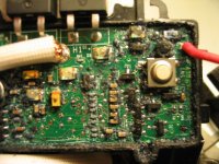
I am not sure what to do with BMS module inside.
But for sure this BMS plays very important role during charging, as Milwakee V18/V28 charger manual says BMS inside battery makes sure cells are balanced, at least it is clearly mentioned , also it is mentioned that BMS senses pack temperature.
I want to use this home -made pack on TF so it must accept regen current I think at least 5A.
All codless tools have some kind otf electric brake, you release trigger electric brake stops it in instant. How does this relates to BMS circuit?
Maybe some of this is return to cells during braking, just pure speculation. DeWalt drill top of the drill gets hot during ripeated on/off trigger use.
It is almost for sure brake at works. I guess drill dumps braking current into some kind of resistor.
I almst decided to disconnect BMS during powering motor and use it only for charging, because.....
I don't have to worry about overcharging , my TF draws theoretically 14A , maybe max15A, so no problems with that, overheting very unlikely with such use.
My concern is how would e-Moli cells take regen current dumped on them.
Any thoughts.
MC
 
Since regen is always pretty inefficient, as long as you used some power before hitting the regen, you should rarely be able to overcharge the pack by regen.

You'd have to watch out for taking a long downhill just after coming off the charger. You'd need to have some kind of safety to prevent overcharging. I'm not sure what the BMS would do.

If the BMS tries to open the circuit upon over-voltage, the back EMF from the motor might be way higher than the rating of the BMS transistor (bad).

The TF controller might have some kind of regen disable for the stock pack if the voltage gets too high. Ever notice anything like that?
 
i'd be watching a voltmeter at least during testing. hit the brakes if it goes to high.
 
Related questions:

If the BMS has 2 FETs, is it safe to assume that one is for discharging and one is for charging?

If a FET opens and burns-up, does it put the cells at risk of damage?

If a FET opens from overcurrent, would that cascade to the next pack?

If Miro's motor draws max 18A, would a 20A fuse in series with the packs protect the packs from a short (provided the packs can handle 20A...see below)?


From http://www.bigerc.com/
Emoli Cell Info

Cell Type IMR26700 Manganese
Size 26mm diameter; 70mm length
Weight 100g
Capacity 3000 mAh
Voltage 3.7V nominal
Continuous Discharge 10-12C
Max 15C Burst
Charge up to 3C
Steel Casing - Very damage resistant.
Charge and balance just like regular Lithium based cells. No need to upgrade chargers or balancers.
Safer Chemistry - Won't combust or thermal runaway


From E-one (Molicel)

Molicel has been a recognized industry leader in the research & development of manganese based lithium-ion cells for the past decade. Using lithium manganese oxide (LiMN204) in the positive electrode of the new IMR26700 cell allows for a Li-ion cell with higher discharge rates than ever before. The IMR26700 cell can deliver currents in excess of 100A.

By eliminating cobalt from the IMR26700 cell it is possible to produce a much larger cell, while providing exceptional safety characteristics. Further developments of the IMR26700 cell will provide fast charge capability, allowing cells to be fully charged in as little as 15 minutes.

Cell Type IMR26700 Manganese
Size ; length 26.4mm diameter; 70mm
Weight 100g
Capacity 3Ah
Standard Charging Voltage 4.2V – 2.5V
Energy Density 285Wh/l
Power Density 1500W/kg at 20 seconds

:)
 
Tghank you for answer!
Yes, TF will not activate regen into battery untill is 20% discharged /one bar lost from SOC/ . It must damp the regen current into some resistor before this happens.
High voltage cut out - never heard of this on TF.
Very good observation about back EMF.
For the sake of saving BMSs I will use them only for charging.
I am planning on connecting WatssUP meter to watch battery voltage, but I am not sure WatssUp can read voltage of the pack. Have to check.
The worse thing I am loosing LV cut out if I am not using BMS.
But wait a minute, I want to incorporate original SOC indicators built into every battery.
Obviously they will not work with BMS disconnected.
But the required to push button on the battery for showing of SOC. I must find a way to BYPASS that push button to constantly display SOC ON 4 BATTERIES.
Still don't know how.
Any ideas on the topic?
MC.
 
This BMS is nearly identical to the Milwaukee BMS (28V).

It may be possible to solder a toggle-switch in parallel to the momentary button, to show SoC.

The black stuff is soft and sticky. It can be cleaned off better than I did.

:D
 

Attachments

  • IMG_2792sm.JPG
    IMG_2792sm.JPG
    86.7 KB · Views: 1,985
Back
Top