Arduino based charge balancer

bobc

10 kW
Joined
Jan 20, 2011
Messages
993
Location
Knutsford England
I need a reasonable cost balancing solution for 10s LiPo & am struggling to find something commercial.
So I thought, - - - - make something.....
A rack of changeover relays can be programmed to look through each cell in turn & measure its voltage.
If the total spread is over 10mV, the relays select the lowest voltage cell and this is charged at 2A for 20seconds.
Then they are all looked at again etc. etc.
Should be simple to build and program and cheap to make (2pole 2throw relays are a couple of quid each, I'd need 9 + an op amp + a small flyback)
What do we think? what's the catch? Has someone done this already?
 
What problem are you trying to solve?

A 10S balancing BMS is a cheap, well understood item.
 
complete battery will be 400A at 120V; not liking the traditional series pass element in normal BMS at this current level. + would like more beef & less dissipation in the balancing function. Lipos give me the power density I'm looking for & considering battery formats, the 10s seem to give best Joules per dollar spent. My usual reaction to not seeing just what I want as soon as I start to look is to start designing....:)
 
I'm just going to smile, nod, and back away from the fireball waiting for a place to happen...

Why are you looking for a 10S balancer if you're building a ~30S pack?
 
400Ah? - no, I want 400A but as few Ah as possible, maybe 10Ah, maybe less: that's why I need LiPo! Its a dragster type thing...
In the past I have run 20C LiPo at 20C (empty it in 3 or 4 minutes) and it was surprisingly happy so I'm expecting that the "nanotech" type things also live up to their specs.
There would be quite a few £70 batteries in this thing so I want something to keep an eye on them & don't want to bankrupt myself. An array of cellogs might do but I'm not very happy about their longer term accuracy, & they don't do the balancing, just tell you when it's out, and the single "error" output is unbelievably flimsy.
Small arduinos are cheap, the programming environment is free and easy and has a wide user base. The most basic would do this job, it just needs an ADC, 5 output ports and a PWM. The extra (shield) board looks like about £20 to get me a custom programmable solution
The whole thing will take a couple of watts; I'm thinking I should supply that externally - I could take it from the batteries being monitored but that would drain 'em. One of the relays is a single dry contact "OK" that I can series up on all the boards in the system.
PS arduino nano costs £3.50
 
I'm going to try this. I can also introduce 2 operating modes
1) balancing mode as described above. Red LED during balancing, status relay contact open, green light when balancing done and status relay contact closes. logging mode now entered.
2) cell logging mode. This cycles round the cells measuring each one every 2 or 3 seconds. The data log is stored on the arduino so it can be downloaded using the USB port. WHen any cell goes below the minimum trip level (say 3V) the status relay contact opens and the logging stops and a red LED comes on.
A switch or jumper on board selects whether it powers up into balancing mode or logging mode.
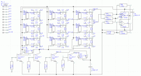
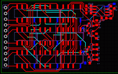
Here's a schematic start & layout start....
chbalance.GIF
chbalpcb.GIF
Controls to the relay array are binary coded with cell position in the string.
Cycling done via a sort of grey code so no spurious decodes and each relay cycles just once or twice every complete sweep
 
Bit more progress with this; I got the arduino nano off ebay, downloaded the IDE - all just works. Unfortunately I need to change the PWM frequency on one of the outputs for the charger flyback & that means installing 3rd party libraries, not got that to work yet.
The PCB is designed, it's 6x7 cm, an 11way balancing port and a 4way control plug (which is isolated 12V supply and OK relay contact output)
Looking at the charger, I need an isolated 2A thing taking its power from the battery total string & I've been looking at the flyback transformer.
I went for an EFD30 core, it's bigger than I need but 40 turns primary and a 0.71mm gap should give me the 260uH I need for 2A output (at 100kHz prf). It won't saturate until near 6A output (what I meant about the core being large enough) and I can actually adjust the charging current by adjusting the prf - may be handy if I do a version for fewer series cells!
I was looking at PCB prices - I might try one of the Chinese suppliers on the web, they were offering prototypes at a fifth the cost of the UK guys!

Day later - arduino library issue sorted, software all ready to go. Better make a board (& get a 10s battery to test it on....)
 
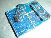
Used PCBway for the circuit boards - $58 for 5 prototypes, arrived after about 10 days (including shipment from China) They look OK, will build up number 1 tomorrow
DSC01640.JPG
The arduinos were £2.40 each. I can control the board directly from the PC over USB or let it do the auto thing. Various LEDs tell me what it's doing.
 
OK there are a few flaws with PCB1. So it will be used for development tests only. The main fault is that the little relays on there need to be driven with a specific DC polarity, I guess they must use a permanent magnet armature to get sufficient actuating force into such a small space. Every relay on there is wired the wrong way round, and because I picked the surface mount version I can't get round this by mounting them underneath. There is no hint of this in any of the documentation I read or on the part itself. So the redesign will use PTH relays (they're cheaper and easier to mount as well), a smaller EFD20 flyback transformer.

Doh
 
bobc said:
OK there are a few flaws with PCB1. So it will be used for development tests only. The main fault is that the little relays on there need to be driven with a specific DC polarity, I guess they must use a permanent magnet armature to get sufficient actuating force into such a small space. Every relay on there is wired the wrong way round, and because I picked the surface mount version I can't get round this by mounting them underneath. There is no hint of this in any of the documentation I read or on the part itself. So the redesign will use PTH relays (they're cheaper and easier to mount as well), a smaller EFD20 flyback transformer.

Doh

Interesting approach.

What relay did you start with that requires polarized DC and didn't document it? That's really annoying.

PTH relays are discontinued, Tyco says. Not that it matters for a one-off.

Do you like PCBway better than OSH Park for boards? I suppose OSH Park is not good for UK though.
 
These are tiny things Alan. When you know, and actively search for it, then you find hints, in this case it was a schematic buried at the bottom of page 2 of the datasheet that had a + by pin 1 and a - by pin 8. It's also frustrating because I now remember making the exact same error about 30 years ago.... (TBH that's why I knew where to look for the lack of response..).
The bigger relays tend to have an iron armature & work either way round. hey hum
PS I was buying this part for about a dollar...
http://docs-europe.electrocomponents.com/webdocs/1398/0900766b813981f2.pdf
It's the first time I've used PCBway for boards, normally I try to use a UK supplier to get reasonable speed delivery. But the UK guys were all expensive, slow, or didn't do 2oz copper. I actually used PCBshopper website, PCBway were 2nd cheapest but got the gig because their website worked....
 
There's been no constructive comments about the system - so just to have another little dig......
my initial plan was to switch on -> balance the batteries -> log cell voltages & flag on the status relay when any one goes over a max or under a min.
It occurs to me that there is no reason not to apply the balancing function at all times (whenever any cell becomes XmV less than the highest voltage cell). i.e.during discharging and charging as well as the traditional balancing blitz at the end of the charge cycle.
I think this has the potential to release more energy from the bank of cells (normally one stops discharging when the worst cell reaches Vmin - the continuous balancing means all cells would reach Vmin at the same time....)
And it could make the bank of cells last longer by mitigating the cycle of decrepitude where the lower capacity cell effectively gets bigger cycles than all its cohorts and embarks on a spiral of doom....
 
Keeping track of trends seems useful. If a cell group needs balancing consistently, that says something about that cell group.

Balancing when the load current is high and the noise and IR drops cause difficulty getting good voltage measurements might not move charge the right way all the time. If that is the goal perhaps turning the converter around and drawing from the high group and feeding the load would be a better tactic. Balance whenever there's load.

Balancing charge current is small compared to load current. So it can only help increase pack capacity if there are lots of stops or other time for the balancing to move much energy, and then only if the pack is significantly out of balance, which would indicate a bad pack.

A good pack generally stays very balanced by itself. I find balancing once a year is adequate. I may do it more, but it is not actually needed. I generally bulk charge and manually check balance and it just doesn't move much.

Judging SOC of each group when there is varying load, IR drops, etc. may be difficult to get any accuracy. Balancing with noisy information may lead to pack unbalance.

There have been a few charge shuffling BMS's, but generally they have faded away. Perhaps the return didn't justify the investment, one tends to never hear the end result.

If a relay sticks you'll have some smoke, but I would expect that you've designed for that failure mode with fuses or some element that will fail on purpose, like a PCB trace.

If you cycle the relays a lot there will be wearout failures there.
 
Alan raises a few points:
in no particular order,
failure modes; the relays are all 2 pole changeover so the most likely fail would mean selection of a wrong cell for measurement or charging, in which case the circuit can't actually make things worse, but won't necessarily make things better any more.
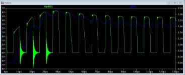
voltage errors during discharge: this is precisely when the LVC cutout in every BMS has to do its stuff, & they seem to work. in simplistic terms you're subtracting IR volts from each cell's open circuit volts, The LiPo R is always impressively low. BTW the 20C rate battery test I did showed the R reducing as the cells discharged resulting in surprisingly low "on load" voltage droop - I'll see if I can find the data log.
Balancing charge rate: unlike conventional BMS, this system efficiently pushes any amount of amps you like into the cell being boosted. Given that the balance leads and connections are rated for 2A, and the relays are rated for 2A, I chose 2A. If we assume discharge at about the 1 hour rate ( most EVs run for about an hour on a charge) and a 10Ah battery, this system as it is can compensate for a 20% capacity reduction in one cell leading to a 2% overall battery capacity reduction,
Lifetime: yeah, it's an issue. Because I switch the charging on and off it's easy to ensure that the relays never ever switch any current. The chosen relays have datasheet "mechanical life expectancy" of 10^8 cycles. If I do a monitoring cycle every 2 seconds that's a max rate on any one relay of 1Hz. So the mechanical life should be 10^8 seconds, or 3 years of operation. For the design application lifetime isn't any sort of issue, in general I'd expect each board to live as long as the battery (LiPo) it's connected to
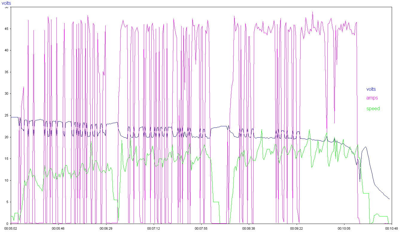
lipolygraph.gif

that's a 6s 2.2Ah Lipo purple is amps, blue is volts
 
I was just thinking about relay failures that I have observed, and two failure modes that were particularly nasty:

1) relays mechanically stuck closed due to migration of internal materials, probably a sealant or cement

2) relays developed shorts internally that were unrelated to the contacts, essentially changing the wiring in unpredictable ways

These were safety rated relays that were not being frequently actuated, so a different type and use case. Not necessarily applicable to this design. but it exemplifies that they were significantly less reliable than expected. They were not subjected to moisture, vibration, or thermal cycling to the degree an ebike will be.

By the way, I'm not attempting to discourage you from your project, I'm just thinking of things I've seen that might be helpful to think about during the design phase. I'd like to see how this works out.
 
The State of Charge readings during the middle of the discharge curve are not very accurate, the voltage differential is most apparent at the ends where the charge state is nearing empty or full. In the middle it flattens out and reduces voltage differences by a large factor. So the ability to judge where to distribute current during the middle of the discharge will be limited. I would expect wiring variances would cause inaccurate decisions to be made during this part of the cycle, especially when variable currents are being delivered to the load. SOC determination is best determined at the ends of the cycle and when current flow is smooth and one-way.
 
Honestly, thanks Alan for conducting a bit of a review & making me think about things, it really is all good as far as I'm concerned :)
The relays are actually specc'ed to cope with crazy G's (like hundreds!!)
The "changeover" nature of the contacts and the fact that they're paired, means battery shorts really shouldn't be possible - it would have to be an "everything shorted together" affair which seems very unlikely and would result in a PCB trace fusing. More likely is an actuation failure or contact welding which would simply make the ADC look at the wrong cell (then potentially charge the same wrong cell....
I agree, solid state would be more reliable than relays, but less accurate & "signal" type data multiplexers won't take 2A... the relays do seem to solve all these problems so long as they keep working!
 
Relays do simplify things a lot, and don't have all the nasty leakage and reverse polarization and spike sensitivity of FET switching arrays. We used to use hundreds of them for multiplexing ADCs long before good mux ICs were made, and the boxes sounded like beehives when running test code. Old memories...

So you're making the relays pass-through to the next so a mis-actuation never causes a short. I like that type of arrangement, though it puts a lot of contacts in series for some of the cells, but for a couple of amps and since it is current based that's not a problem.

Nice.

I've run out of issues to suggest.
 
Alan B said:
boxes sounded like beehives when running test code.
Like it - I'm scanning the cells on a sort of grey code sequence (only ever 1 relay switching from one check to the next) and that also minimises the total number of relay clacks.
I've not debugged the charging flyback yet (should be able to do that at work tomorrow) - it needs some 'snubber' components to be sorted, other than that I'm ready to send off the gerbers for version 2 (the final version???). The board has actually gotten about 10% smaller, quite nicely sized to go with a 10s Lipo brick!
I can put the gerber files BOM & arduino code on here if anyone 's interested?
 
Back
Top