titusmc
100 W
Hi ES,
I've been in the process of building five 14S8P 18650 packs over the last few months (whenever I have time) and it's made me think a bit about fusing. This video by 15-sec-of Fame https://youtu.be/5EE4TsuzD_Q convinced me to build one pack using PTC fuses (4A) at the cell level. The argument for the fuses, as I understand it, seems to be that if a cell internally shorts the fuse will prevent the other cells in the parallel group from dumping lots of current through the shorted cell, thereby avoiding a fire.
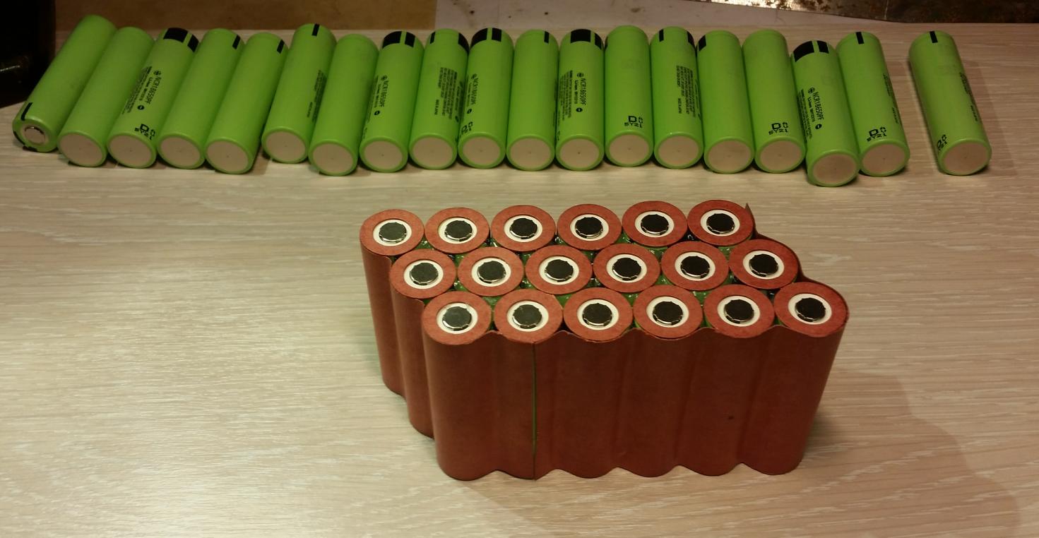
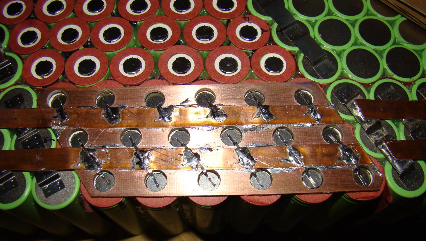
Here's my most recent build featuring these PTC fuses.

Doing this is kind of a pain, since it requires lots of very careful positioning of the fuses, anchoring with tape, and careful soldering. That's why I'm questioning it - I can certainly make packs faster if I just use tinned copper braid for all connections.
It seems like almost no one does this cell-level fusing on ebike packs, commercial or DIY, so the question I have is - is this overkill for safety? I certainly don't want a fire, but I also feel like the risk of having one this way is extremely low (with no real data to back that feeling up). Does anyone know more about this type of failure mode - that is, parallel cells dumping current through an internally shorted cell? Will a 4A PTC fuse actually help or could <4A through a shorted cell still result in a fire?
Side note: I have been using an 80W Weller chisel-tip iron from amazon and it is amazing for soldering cells quickly. I just tinned both terminals of 112 cells and added bus bars on the negative of each parallel group in about 2 hours. My contact between cell and iron only lasts about 5-10 seconds at most with the 80W Weller.
I've been in the process of building five 14S8P 18650 packs over the last few months (whenever I have time) and it's made me think a bit about fusing. This video by 15-sec-of Fame https://youtu.be/5EE4TsuzD_Q convinced me to build one pack using PTC fuses (4A) at the cell level. The argument for the fuses, as I understand it, seems to be that if a cell internally shorts the fuse will prevent the other cells in the parallel group from dumping lots of current through the shorted cell, thereby avoiding a fire.
Here's my most recent build featuring these PTC fuses.
Doing this is kind of a pain, since it requires lots of very careful positioning of the fuses, anchoring with tape, and careful soldering. That's why I'm questioning it - I can certainly make packs faster if I just use tinned copper braid for all connections.
It seems like almost no one does this cell-level fusing on ebike packs, commercial or DIY, so the question I have is - is this overkill for safety? I certainly don't want a fire, but I also feel like the risk of having one this way is extremely low (with no real data to back that feeling up). Does anyone know more about this type of failure mode - that is, parallel cells dumping current through an internally shorted cell? Will a 4A PTC fuse actually help or could <4A through a shorted cell still result in a fire?
Side note: I have been using an 80W Weller chisel-tip iron from amazon and it is amazing for soldering cells quickly. I just tinned both terminals of 112 cells and added bus bars on the negative of each parallel group in about 2 hours. My contact between cell and iron only lasts about 5-10 seconds at most with the 80W Weller.

 , unless you have some kind of protection system or protocol.