Qulbix Q76R 18650 battery build

Quokka

1 kW
Joined
Feb 9, 2016
Messages
305
Location
Perth, Western Australia
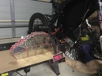
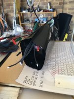
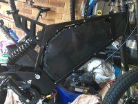
I have been asked by fellow members to show the battery build for my new Qulbix.
Before i kick off a few disclaimers. This was my first battery build and i am definately not a battery guru. There are many different ways of making batteries and this is by no means the "best way" but it was the way that made sense to me at the time of the build given the materials and batteries and welder i had access to.

Important!!! These batteries are dangerous. A mistake could result in a serious fire and as such they need to be treated with caution and respect.


Now.... On to the build.

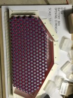
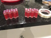
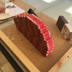
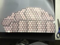
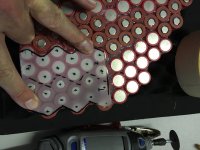
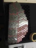
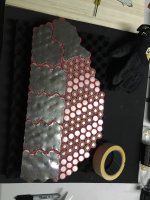
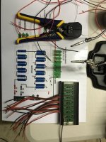
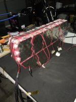
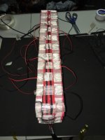
My aim for the battery was to build something that maximized the capacity of the frame and to get some pretty decent amperage. I decided on a 20s 12p battery.

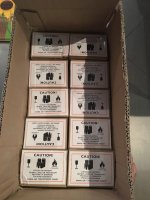
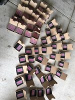
The cells i chose were the 3500ma Sanyo GA cells. If building the pack again i would probably go for Samsung 30Q cells as they can deliver 30 amps vs the sanyo's 10 amps for not much less capacity. I had massive issues with freighting these due to a change in lithium ion battery transport regulations. Hopefully the couriers sort this out soon as it was nearly a show stopper for me.
 

Attachments

  • image.jpeg
    image.jpeg
    84.7 KB · Views: 4,394
  • image.jpeg
    image.jpeg
    114.3 KB · Views: 4,394
The layout of the cells was based on an irregular pack design. I printed out the frame opening availible on the Quilbix website, checked it against the frame opening ( was a little smaller than the real opening i had) and strated packing in the cells to try out different scenarios
 

Attachments

  • image.jpeg
    image.jpeg
    119.7 KB · Views: 4,398
To make the parralell groups, i hot glued them together, and then added a layer a fibrelass reinforced tape. The tape is there to add a little bit of a gap to help protect from chaffing and to add a mitigation to a possible short between groups. Individual cell holders are great for this, but the cost of cell holders comes at the expense of how many cells you can fit in your bike.
 

Attachments

  • image.jpeg
    image.jpeg
    68 KB · Views: 4,383
I then glued together all the parralell groups. This is hard... You need to work fast, the glue hardens quickly. For this reason you need a good hot glue gun.
I also added paper gaskets to the positive ends of the cells for short protection
 

Attachments

  • image.jpeg
    image.jpeg
    98.3 KB · Views: 4,391
The method of making the parralell and series connections was to use .2mm pure nickel sheet. I used around 1.2 meters of sheet that was around 20cm wide. This stuff is expensive... The reason i chose .2mm was it was the minimum thickness i could get away with to achieve 80-100 amps. The thread "18650 the ultimate guide" has a great guide on material vs current characteristic. Remember, thick nickel is hard to weld and copper has a poor mechanical strength which i felt could cause an issue if/ when i stacked the bike.
 
After you have the templates you need to trace outlines onto the nickel sheet and cut them out a pair of scissors
 

Attachments

  • image.jpeg
    image.jpeg
    39.2 KB · Views: 4,379
I also marked the locations of the welds on the tracing paper to make sure i wouldnt inadvertantly make a weld in both the positive and negative on a cell. I used a dremel to make a small mark on the nickel
 

Attachments

  • image.jpeg
    image.jpeg
    78.5 KB · Views: 4,389
  • image.jpeg
    image.jpeg
    65.5 KB · Views: 4,389
  • image.jpeg
    image.jpeg
    44.6 KB · Views: 4,389
Now its time to fire up your welder and get serious. Make sure you have glasses and gloves on. After i attatched a sheet of nickel i taped some cardboard over it for a saftey barrier in case of a short. Also, take any metal off you. Watches, belts zipps etc.
 

Attachments

  • image.jpeg
    image.jpeg
    57.1 KB · Views: 4,381
  • image.jpeg
    image.jpeg
    66.6 KB · Views: 4,381
  • image.jpeg
    image.jpeg
    78.5 KB · Views: 4,381
  • image.jpeg
    image.jpeg
    76.4 KB · Views: 4,381
  • image.jpeg
    image.jpeg
    105.9 KB · Views: 4,381
For a bms, i am utilizing an adaptto. I made 5 4s jst balance leads using silicon wire. I wrapped the balance wires in an expandable sheath to keep the spider web of wire under control
 

Attachments

  • image.jpeg
    image.jpeg
    93.2 KB · Views: 4,360
  • image.jpeg
    image.jpeg
    84.6 KB · Views: 4,360
  • image.jpeg
    image.jpeg
    84.8 KB · Views: 4,360
Now, i ran the leads to their respective group for soldering
 

Attachments

  • image.jpeg
    image.jpeg
    76.5 KB · Views: 4,358
  • image.jpeg
    image.jpeg
    67.7 KB · Views: 4,358
Awful lot of work , skill, time and care required there...Well done.
did you test/check or balance the cells before assembly ? ..
I know they are quality cells, but its a lot of work to find & replace any bad cells after the build is complete.
 
Ok.. Lets finish this thing off.
I cut out a piece of 3mm acrylic to protect the base of the pack and bent it to shape using a heat gun slowly working across where i needed to bend it to shape. I then hot glued it to the base of the pack for protection. I then cut out some 3mm self adhesive foam for the protection of the side of the cells.
Once this was done i wrapped the whole thing in giant heatshrink.
It just fits by a whisker- had to dremmel a tiny bit on the frame to get it in
 

Attachments

  • image.jpeg
    image.jpeg
    97 KB · Views: 4,253
  • image.jpeg
    image.jpeg
    104.2 KB · Views: 4,253
Back
Top