Another 18650 stack build

bobc

10 kW
Joined
Jan 20, 2011
Messages
993
Location
Knutsford England
I found some 5Ah 18650s on ebay for less t ha £1. Wow I thought. A bit of digging on "Hi capacity power products" reveals that they print 5000mAh on the cells but they deliver just 1000mAh and the price is the expected £1/Ah/cell. Bit surprised to see such blatant lies from a 'big' supplier.
Anyway, regardless, started looking at how to stack these things & came up with using a 100mm diameter 'soil pipe' with 19P cells inside - stack as many s as you want (11s is 40V and ~750mm long). Just wondered if anyone else had used this system already - it would appear to be quite attractive
 
:?:

https://endless-sphere.com/forums/search.php?keywords=18650+pipe&terms=all&author=&sc=1&sf=firstpost&sk=t&sd=d&sr=topics&st=0&ch=300&t=0&submit=Search
 
Thanks very much mr wolf - 1st search hit https://endless-sphere.com/forums/viewtopic.php?f=14&t=69738&hilit=18650+pipe is spookily close to what I was thinking (identical but scaled down, 7p instead of 19p). I think I'll make one of these for my trike (too late for the emax) in 12P guise

I'll drop a couple of pictures on here....
 
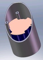
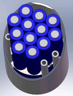
here's an assembly picture - don't know if it makes great sense - you can see the copper sheet that connects all the parallel cells, and the tab on it where the balance wire solders. The tubular rods keep everything in place & have m5 studding down the middle to hold it all together. Make it as many series as you want, just keep lengthening :)
12passy.jpg
I'm struggling with the economics of the system though, I paid 1GBPound per amp hour for prismatic lifepo4 cells. The 18650s all seem to be about double that:- who is the cost effective supplier that I can't find???? Or is the attraction of 18650s the flexibility, not the price..?
 
Thanks HH -
I still can't see anything better than $1.4 per Ah, then you've to add in shipping and all the work & fabrication to wire 'em all up. I had discounted the "import a shed load from china" option as way too risky (particularly in this cell size it seems, the use in lasers and e-ciggies seems to have opened the door to ludicrous false capacity claims. I've seen claims of 5Ah, 8.8Ah etc) I suppose that buying genuine Samsung/Panasonic/luckygoldstar/sanyo should ensure you receive the amp hours advertised but also seems to ensure nearly double cost per capacity.

Where are the "economies of scale" from tesla & the much hyped "gigafactory"? To be fair I think they have only talked of a ~33% saving . . when the place is fully on-line (in a couple of years?)

disappointed, I was hoping for more when I started to look at this.
 
Thanks PB, that actually works; there are some Samsung 2.9Ah on there that would just cost me £0.82 per Ah (including delivery) for a 12P 6S stack. (£173 total)
The housing (e.g. above) would cost a bit - time mostly. Maybe I will go ahead with this for the trike :)
 
bobc said:
Thanks PB, that actually works; there are some Samsung 2.9Ah on there that would just cost me £0.82 per Ah (including delivery) for a 12P 6S stack. (£173 total)
The housing (e.g. above) would cost a bit - time mostly. Maybe I will go ahead with this for the trike :)
Take a look at Sanyo MG1 for middle power cells.
 
Just a slightly better picture. A 6s version of this would be 35Ah & cost £173 in batteries. Not bad :) Here's a better picture
12passy.jpg
It would be pretty light & strong and could be properly sealed. 6s 35Ah would be 80mm outside diameter and ~400mm long
 
Found a few GRP tube suppliers on line - asked for a quote for the 9mm diam "screw tubes". I'll do a dxf to get the copper plates routed. Oh yeah - I need to get some copper plates....
And... I just spent £12 on a piece of tube for the outside and £173 on 6s 12p batteries at 2.9Ah
 
I figure 0.8mm should be strong enough while still allowing a small amount of 'give' to conform to manufacturing tolerances of individual cell height.
I'm going to copy someone on here & solder small brass nuts (M2.5) on one side to connect to the flat battery bases.
 
it's probably better to make dents in the copper plates with the battery pattern. much less issues with soldering brass nuts and the increase of things to let go and cause issues.
 
If I were going into business making scores of these, I would jig it properly & indent bumps like you say. For 1 off I'm sure I will get better thickness control with the nuts soldered on....
BTW just spent another £6 on copper plate....
 
Cylinder ends will be substantial. I might rout 'em out to lose a bit of weight while retaining 15 to 20mm thickness ribs
6 off M5 studding through length to pressurise stack (through the holes in the smaller grp tubes)
1 piece closed cell foam "spring" between cylinder end and top copper to push on all cells
plenty of Vaseline....... (to stop contacts corroding) And think positive thoughts... :)
OK I just spent £7 on some 15mm thick acrylic for the end caps - I should be able to make all the bits in the next week or so.
 
bobc said:
If I were going into business making scores of these, I would jig it properly & indent bumps like you say. For 1 off I'm sure I will get better thickness control with the nuts soldered on....
BTW just spent another £6 on copper plate....
Bobc, you are going to need several of these copper contact plates, each with numerous contact points.
...thats a lot of nuts and soldering !
I know You have the skills and facilities to make a simple "single dimple jig", for use in a bench press/drill stand/hammer,
......and it will save you many hours soldering. The jig can set the dimple height accurately also.
 
I have a plan for the soldering (involving the kitchen gas hob....) - if it works it will be a piece of cake - if not, other solutions will be considered!!!
I'd use paste & stick 'em down the reflow line at work - but I suspect they wouldn't let me.....
(yes stick the nuts on in place with a blob of solder paste then light the hob under the plate. When the solder melts - turn it off....)
 
Saw the design in solidworks in person with Bob. I can say this, the projection used here in photos doesn't do this design justice. It has a good symmetry so all cells should get equal pressure. We worked out that we could adapt this to fit our E-max 110s scooter and fit about 110ah at 80v which almost doubles what I can do with lifepo4 at the moment, with considerably less weight I might add. The projection end on is a better one but I understand why Bob used the diagonal cut away to expose more of the internal design.
 
I had another look at this & the 110Ah assumes the large CSA of the battery "box" all the length. So it's actually not quite so good.....
But a 55Ah string made of 2 torpedoes would be lots more energy than the SLAs in a reasonably compact format, and an extra parallel 35Ah could be fit in easy enough (90Ah at 80V).

The 55Ah is a 19p arrangement - this fits nicely in a 100mm pipe. 19p20s would give 80V at 55Ah and cost ~£850 in raw 18650s. The cost of associated parts, copper, pipes, end caps etc is low - £20 or £30

Parts for the test assembly should start arriving over the next day or 2

PS best fit in the emax would be 3 x 20s strings of 12p (in 80mm od tubes) which would be 105Ah if you used 2.9Ah cells. You would get very bored going well over 100 miles with that lot in.....
TBH this level of on-board energy would be very suitable for increasing the speed and power capability - it is over 4kW (the motor nameplate) for 2 hours; sounds right for a speed increase to 50+ mph (the extra volts should allow it) and probably ~80 miles range. Would be dependent on motor temperature....
 
OK stuff started arriving, reality is slightly disappointing:
1) the acrylic tube I bought is less than 74mm inside diameter; the batteries (also here) do go in but they're a tight fit & I'm not happy with it. So I've bought some alternative 75mm ID tube - should come at the weekend.
2) the batteries are here. I was surprised to learn that BOTH ends are actually ever so slightly recessed c/w the plastic 'sleeve' they're built into. So there's no way either end will connect reliably to a flat copper sheet, or one with a raised 'dimple' (or whatever) on just one side. I'll have to 'dimple' one way AND solder a nut on the other side - looks like a bit more effort than I was hoping. At least the 'dimpled' recess will positively locate the raised nut while soldering.
C'est la vie
 
A few suggestions that might help you. I have built several packs similar to what you are doing and after working out the problems they do work well. Take a look at this https://endless-sphere.com/forums/viewtopic.php?f=14&t=69738

If you have access to a table saw you can run a cut lengthwise to allow the cells to fit into a slightly small tube. There is a photo in the above thread showing this.
I cut a small ring from the neg side wrapper of the cells so they can contact a flat copper plate.
Near the bottom of page 2 of that thread there is a list of 9 suggestions.

Keep at it .
 
Yes , I saw your post (AW linked to it above) & this is clearly a case of great minds thinking very much alike :)
I don't want to saw down the housing, (mechanically weaker and unsealed) so I've bought a slightly bigger tube (worryingly specified as 80od,75id and 2mm wall.....??)
Also, I'd prefer not to butcher the cells - I'll dimple + nut solder.... (sigh)
I want to completely seal the housing and install one of those Gore-Tex breathers, the batts should generate enough warmth to keep them dry through the goretex vent: - a dry environment + Vaseline should hopefully keep the contacts good.
 
Back
Top