Help wire my BMS

Blessbeast

1 µW
Joined
Dec 6, 2016
Messages
1
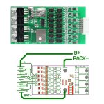
47628-2.jpg This is very confusing for me and i dont wanna screw things up :/ so could someone knowlagable tell me witch pins go where and where is the charger input since output will not be going through the BMS, sry but this is all the information Ebay gave me to work with :( This is the link if its any use.. and thank you in ahead ^^ http://www.ebay.com/itm/7s-Cells-24V-20A-W-Balancing-Li-ion-Lithium-18650-Battery-BMS-Protection-Board-/272315777944?hash=item3f67490398:g:y6gAAOSw4s9XkbJG
 
If you want this for charge only, you’ll need 2 sets of leads from the battery terminals. One should be heavy gauge capable of handling the current for your controller. Those wires should never see the charger.

The other leads from battery terminals will be “charge only” and unless you’re doing something ridiculous, they can be gauged much smaller than the controller wiring. This set of leads will only connect to battery-BMS-charger.

One problem with the drawing is the label “PACK -“ which looks like a misprint. "P -" = Power in/out. As charge only you’ll be sending power into the battery through the BMS.

So the pack is wired to “BAT -” lug on the PCB and “P -“ pads on the PCB for the negative charger-battery leads. The drawing is also flipped upside down in relation to the picture but use the “P -“ for your charger connection. "B +" will only connect to the BMS via the small cell channel wires. But you will need a run of wire for "B +" between the POS + battery terminal and charger POS + connection.

Then of course you need to wire in the cell level or (channels) connections. Follow as drawn and you should be good to go.
 
Look at the 8 pin jst connector that is on your pack, unless you are building the pack from individual cells. All wires EXCEPT the negative wire are connected to the bms. This is because the negative will already be connected to the board thru the main negative lead from the battery.
 
Hope it is okay if I borrow your thread instead of making a new one..

I am having some trouble with the same BMS as Blessbeast. I have connected the wires as I am used to, since there is only 7 sense wires for a 7s BMS, they only go to the positive of the cells and not the first negative. The first negative I connected to B-. The funny thing is when I connect the B- from the BMS to the most negative cell, I measure 8V through the BMS P- wire and the positive end of the battery :eek: Directly measuring the battery gives me the full voltage (28V at the moment).

Did I do something wrong? Or is it possible this cheap BMS is broken?
 

Attachments

  • IMG_0120.jpg
    IMG_0120.jpg
    157.6 KB · Views: 2,333
Solarpower said:
Hope it is okay if I borrow your thread instead of making a new one..

I am having some trouble with the same BMS as Blessbeast. I have connected the wires as I am used to, since there is only 7 sense wires for a 7s BMS, they only go to the positive of the cells and not the first negative. The first negative I connected to B-. The funny thing is when I connect the B- from the BMS to the most negative cell, I measure 8V through the BMS P- wire and the positive end of the battery :eek: Directly measuring the battery gives me the full voltage (28V at the moment).

Did I do something wrong? Or is it possible this cheap BMS is broken?

The correct way is on the left, you must have it like shown on the right. The red lines are the connections to each series cell and orange is the bms wires.
http://i.imgur.com/bYNfu1t.png
 
I found out that I did it wrong the first time, I hooked it up like I'm used to with other boards like B+, B2+, B3+ and so on... So I took "+" and connected to the first positive cell :roll:

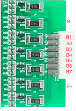
I bought a new one, and took another look at the wiring diagram. The JST connector first pin, "+", is obviously going on the packs most positive cell(25,9V). And "1" is going on the second most positive cell(22,2V) and so on... The first cell negative is going directly to "BAT-" on the board.
Can someone confirm this for me? This is the way I did it now, and still only get a few volts on the multimeter... :cry:
 
B+:cell nr 7=29.4v
B1=4.2v(so not 25.2v)
B2=8.4v
B3=12.6v
B4=16.8v
B5=21v
B6=25.2v

B- wil be the negative for this type bms so this is correc.the rest is wrong,you start@the wrong side...always start from the negative...the first positieve in the serie you have =B1+ 3.6v nominal
 
The thing that got me confused was the figure showing B+ and then continuing with B1 and so on.. But it makes sense when Joachim lists them up like that.. Just does not correspond well with the drawing provided by the seller (in my head at least).

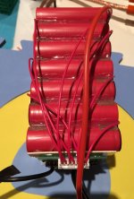
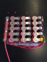
silviasol, I have marked on the pack where each JST wire goes, and B- that I connected to BAT- on the BMS. Does this look correct?

Pack1.jpg


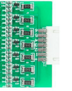
The wire number on the pictures corresponds to this one:
BMS.png


Thanks for your help guys.
 
Thanks Joachim! :) One last question.. Just to see what happened, I connected the JST connector to the same BMS that I did last time, only now the right way :p And it started smoking! Could this happen because I broke it last time, or is it something funny going on?
 
if this is the case then they put the numbers wrong on the bms!!most bms boards i have seen always have B1 for the first positieve(4,2V) in the serie...B2 the second 8.4volt and so on...
 
Do you understand my frustration here? :roll:

silviasol, can you confirm that I know understand you correct? Thanks :D
BMS.png
 
buy a proper bms with correct cell numbers on the pcb....this is strange how they put the B+ nr 7 and the rest of the numbers :lol:
 
Solarpower said:
The thing that got me confused was the figure showing B+ and then continuing with B1 and so on.. But it makes sense when Joachim lists them up like that.. Just does not correspond well with the drawing provided by the seller (in my head at least).

silviasol, I have marked on the pack where each JST wire goes, and B- that I connected to BAT- on the BMS. Does this look correct?

View attachment 1


The wire number on the pictures corresponds to this one:
View attachment 2


Thanks for your help guys.
why dont you have parallel connections on the positieve sides??
 
Because it looks like shit :lol: :lol:
https://endless-sphere.com/forums/viewtopic.php?f=14&t=26383&start=1400#p1212568

Or you could take a look at this:
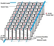
Li_SP.jpg
 
the battery have the parallel conections and this will wurk...but you can put a extra strips on the positieve sides...this makes the pack stronger so why not?
 
Back
Top