Cheap sub $10 Solderless 5S6P pack build

myzter

1 kW
Joined
Aug 8, 2008
Messages
411
Location
Van, B.C.
- - This is EXPERIMENTAL - - -
Please DO NOT attempt this solderless build method unless you are an Electrical tape PRO

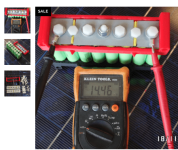
One of my 5S - 8Ah Nanotech packs was down to 2Ah usable, barely enough to get to work and back home..
I needed to build a pack with SONY NC1 cells I`ve had sitting in a box for the past 2 years...
Many ideas for solderless packs around.. most require purchasing plastic pieces or 3D printing
the lack of funds have prevented me from spending a couple hundred dollars on a spot welder and hardware... or a 100Watt soldering gun.. so I set-out to construct the lowest cost battery pack with readily available materials..
total cost to build = $0

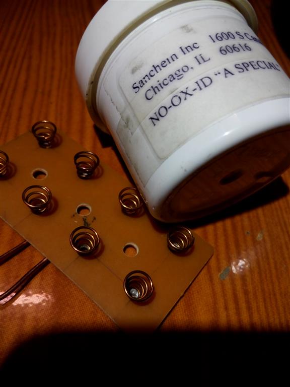
.high strand tinned wire
.electrical tape
.wood stir sticks
.polycarbonate
.stretchy rope

1.jpg
2.jpg
View attachment 8
4.jpg
5.jpg
6.jpg
7.jpg
8.jpg
9.jpg
10.jpg
11.jpg
Fairly straight forward... The next rebuild I might try to use maximum strength - high temp duct tape to secure the cells.
Any questions ??
 
you've just wasted a lot of time on something that's on the best case will give lots of contact resistance, on the worst case will cause imbalanced P groups and possible explosion due to reverse charge

spring contacts w/ grease would be far more reliable of limited to about 3A per cell:

pZND70z.jpg


i also have a soldering technique that takes less than 1 second w/ the iron so there's no excuse :twisted:

[youtube]0ZRwMXL-Rvs[/youtube]
 
Gee thanks for telling me Im wasting my time and then posting hijacking my thread and posting all your details which have nothing to do with the thread topic... further wasting my time by the way!!!

Ive measured IR with my ICharger and the 5 strings show 9-10-10-11-10 (without any conductive grease)

Additionally ... I have been riding in sub-zero temps for the past two weeks with my first solderless pack.. WITHOUT ISSUE!!
pulling 2KW peaks! +20kph wipe-outs - end over end.. OH did I forget to mention I was riding an Electric Snobike !

SnoBike2016-17-2.jpg
sorry peeps for the terrible pic..
 
I have to agree this pack is shady and I think it is on topic to discuss other alternative ways. I trust the the previous posters method more than I trust your. But to each their own if it works for you it works. There is definite room for improvement on you design. I don't think its mechanically sound.... The pack as a whole or the electrical connection for low id consider a friction contact setup but for higher amps I'd have to choose spot welding or soldering. You mentioned high top duct the. If you are getting the cells warm enough to need to go to a higher grade.. One you may be pushing the cells to hard and two your connections could be creating points of high resistance connections which causes heat. . Cells can show good under no low and have good IR but put a significant load and plot it on a good charger on it and all the faults in this design will be come apparent
 
Yeah okay, but If you want to change the direction of the subject material and discuss alternative ways then start a new thread ?? makes sense to me.. Im trying to develop this idea as far as I can.. It is only a first step.. I mentioned High temp duct tape NOT because the cells are overheating.. but because of heat in summer months or hotter climates. However using tape is not my ideal solution.. I would like to encase the cells in fibre and resin which is alot more work and cost that Im not in a rush to get into..
 
I don't think this pack is as bad as it looks at first. In fact, for a taped-together design it's pretty good. The high-strand wire is flexible and conforms to the cell terminal surface, giving a better contact. The wood splint both ensures the force of the tape is applied to the wire (rather than the tape stretching around the wire) and also acts a spring to maintain contact pressure. The electrical tape used is also stretchy. As long as it's for low-power use my only real concern would be the tape relaxing (either itself stretching or the adhesive slipping).

I'd compare it to the early NiMH Zero motorcycle packs that used similar rows of cylindrical cells with copper braid laid across their terminals with lengths of rubber inner tube to hold them in place, then the whole lot covered in heatshrink tube. That's a better alternative to tape IMO.
 
thankyou Punx0r
If we were in summer and hot weather .. the tape slipping is probably my main concern.. I have been looking at the many heavy duty duct tapes available.. However using this much tape is only temporary.. I would like to transition into using heat shrink and fibre resin wrap..
 
Not sure wood is the best choice.. something that doesn't hold moisture might be better.

Let's just say the resistance goes up over time. ... Is the positive terminal wire going to melt thru the can wrapper and short or is it gasketed enough?
 
Good points Voltron

more gasket needed
wood alternatives also
 
Fibreglass circuit board could be used in place of the wood and heat shrink tube over the tape to mitigate the possibility of the tape slipping or relaxing.
 
http://www.batteryblocs.com

Neodymium magnets
 

Attachments

  • Screen Shot 2017-01-05 at 2.18.40 PM.png
    Screen Shot 2017-01-05 at 2.18.40 PM.png
    81.8 KB · Views: 3,178
A good gasket material is called Fish paper.. and should be used anyplace a wire is in contact with the cell can
fibreglass instead of wood.. might work if the sharp edges can be filed down as to not cut the electrical tape

thanks tomjasz anybody could find the many other thread posts for batteryblocs or other DIY builds if they were trying.. I know I had seen them before.. so lets try and keep those ideas to the other threads If you could somehow manage it.. Im not going around hijacking their threads.. but lets compare

I would need to buy 3X 6P-2S item at $12 each and add shipping to Canada.. so lets say atleast $50.. where my build would be under $10 and because I already had materials it cost me $0.
Not too mention the added weight of magnets, metal nuts of 3x blocs

However another point is individual cell level fusing.. which I can be put in place in my design..
 
Seriously? hijacking is now posting a comparison? I have no interest, but see serious issues with your design. Combining ideas often makes for interesting improvements. I posted as a source of potential improvements. No different than overclockers add.
 
ok fine .. my mistake.. I should have set-up the topic of the thread properly.. I wanted this to be about lowest cost alternatives to soldering-welding .. and see if the community could come up with improvements we can all source locally..
 
Not to mention the very bad resistance (very high resistivity) of neodynium magnets.... I wonder if the very thin nickel plating on those magnets helps in any significant way to reduce that crazy resistance of neodynium alloys.

We need an experiment : pull at the very lest 10 amps (if not 30 amps from VTC4) through that quarter inch diameter, 2 mm thick, dicoid neodynium magnet and see how bad the temperature rises is in a closed environnement. I'm pretty sure it's bad for medium to high amps applications. Please prove me wrong and i'd buy a lot of those battery blocks. I'm still skeptical on the resistance issue.

We want specs before we buy. Resistance values for the magnets ? And what about those 0.7 mm thick steel metal conducting plates ? Overall resistance ?
 
I got one of these the other day, I think you should get one too! https://www.fsmgarage.com/p/76

Macgyver would be proud with the effort you've gone to using stuff you have around.

The other forum members are not trying to nuke your thread with other ways of making a pack, rather, they are trying to steer you in the direction of safer pack building to produce packs which will last longer and have less risk. You may be interested in forum member Snath's packs, as he has pretty much nailed solder/weldless pack designs in a way that will be robust and safer over time.
 
myzter said:
I wanted this to be about lowest cost alternatives to soldering-welding .. and see if the community could come up with improvements we can all source locally..

I'm with you. Could I respectfully suggest you are also considering "ultra fast build, with low learning curve and low equipment cost?"

Since the electrical tape is your spring, I wonder if the cold reduces or increases the pressure. Maybe hang a weight on it against a ruler, then leave it outside for a bit, see if it stretches. I wonder if the duct-tape would give more or less pressure variation from winter to summer than the PVC tape? I think duct-tape is just as susceptible to creep as electrical tape is.

Vancouver is now generously seasoned with road salt. Hope you have it well sealed out of your pack. It certainly has made it into my chain. I haven't done any endo's yet, but I have made some low speed side-o's. I'm too cheap for studs. A friend recently broke his shoulder falling off his bike. :shock: But he's old too, and grew up where there was no ice.

What is your idea for heat shrink and plastic resin wrap? What would provide the spring force?
 
Matador said:
Not to mention the very bad resistance (very high resistivity) of neodynium magnets.... I wonder if the very thin nickel plating on those magnets helps in any significant way to reduce that crazy resistance of neodynium alloys.

We need an experiment : pull at the very lest 10 amps (if not 30 amps from VTC4) through that quarter inch diameter, 2 mm thick, dicoid neodynium magnet and see how bad the temperature rises is in a closed environnement. I'm pretty sure it's bad for medium to high amps applications. Please prove me wrong and i'd buy a lot of those battery blocks. I'm still skeptical on the resistance issue.

We want specs before we buy. Resistance values for the magnets ? And what about those 0.7 mm thick steel metal conducting plates ? Overall resistance ?
We'll see, that's what we do here. Take an idea and wring it out. It may be worse than the OP design. But let's do it with data. K?
 
tomjasz said:
Matador said:
Not to mention the very bad resistance (very high resistivity) of neodynium magnets.... I wonder if the very thin nickel plating on those magnets helps in any significant way to reduce that crazy resistance of neodynium alloys.

We need an experiment : pull at the very lest 10 amps (if not 30 amps from VTC4) through that quarter inch diameter, 2 mm thick, dicoid neodynium magnet and see how bad the temperature rises is in a closed environnement. I'm pretty sure it's bad for medium to high amps applications. Please prove me wrong and i'd buy a lot of those battery blocks. I'm still skeptical on the resistance issue.

We want specs before we buy. Resistance values for the magnets ? And what about those 0.7 mm thick steel metal conducting plates ? Overall resistance of the system ?
We'll see, that's what we do here. Take an idea and wring it out. It may be worse than the OP design. But let's do it with data. K?

Honestly I totally love the idea and almost instantly ordered it online from your website. But then I realised that since Neodynium adds significant resistance, I might wait for other peoples's feedback on it... or for some datasheets of the product to come out...

Specifically, neodynium has a resistivity of 1.47 (±0.37) x 10^-6 Ohm.meter (at 25°C). Not so high as I originally though tough.... Well not so significant considering the short path lenght and high cross sectional area for the current to pass throught the magnet....
So for a neodynium magnet of 6.35 mm diameter (Pi.r^2 = 31.7 mm^2) and 1.75 mm thick, that represents only 0.08123 milliOhm resistance per magnet (thanks to short lenght)... NOT BAD AT ALL.

BUT, you specify they are NICKEL-PLATED (what plating thickness ?) neodynium magnet. So since nickel has a lower resistivity than neodynium, I THINK that overall resistance will be even slightly better if noticeble.

I understand that there isn't much choice except to use 1010 steel as the connecting plates (neodynium magnets won't stick to copper, aluminium, brass or nickel) .... At least it it's 0.7 mm thick, 38.1 mm width and 76.2 mm lenght, the high resistivity of 1010 steel (1.43 x 10^-7) will be compensated by the thickness of the material. NOT BAD AT ALL.

If the connections have enough magnetic force, there hopefully wont be much added contact resistance to the total resistance....
Actually this could work.

I just wonder what's the resistance and ampacity of your system as a whole (sombody up to some cycle analyst calculations ?). If the resistance results in heat up from the metal contacts, that could secondaryly heat up and reduce the usable number of cycle life of the 18650's through diathermic transfer. Please keep us posted if you get any results, either good or bad, I was personally a heavy believer and enthousiast about soderless solutions but I had chosen the spring path a the time : https://endless-sphere.com/forums/viewtopic.php?f=14&t=57810&start=150#p1213147

I plan on using very very high-drain cells on my build. Sony VTC4 rated a 30A discharge... I'm still interested in your product but I would like to see it perform on an eike first. Moderate power range (1.5 to 3 kW at 52V).
 
Not my product but my experiment. Reported resistance is low, I'll be able to provide whatever relaventbdata the CA 3 provides. Sadly it won't happen quickly it's a bitter winter this year. Near zero F temps don't make for good test parameters.
 
To be fair ive bought a soldering iron on ebay before for 25cents free shipping and it came with solder. 3m 1700+ tape sells for $1.44 a roll and 33+ sells for $5 a roll. I dont mind the pack design but i feel it would have been cheaper to solder. Im not sure if you have the skills to yet but it can be learned fairly quickly. Also there are many neat do it yourself spot welder kits around which are a fun project of thier own. Also it would be smaller and lighter soldered. Good first pack but lots of room for improvement.

This is coming from a guy who mounted an entire 48v 10ah lifepo4 battery inside my mountain bike frame with nothing but four rolls of 3m tempflex rubber tape and four rolls of regular electric tape. I shit you not video in my signature from years ago.
 
Solder is a worse conductor than copper thats while I will use a silver product on the contact points and wire connections for my next rebuild.
Volume resistivity
Silver 0.0001Ohms-cm
Nickel 0.0068 Ohms-cm
Carbon 0.46 Ohms-cm

ANYWHO!!
Here we have more results from the main topic of this thread..
5s6P 16Ah 18650 pack, wired in series with a Nanotech 5S2P 16Ah paralleled pack powering a 2Kw electric SNOBIKE...
This is pretty tame first ride... Since then I have gone full throttle in powder for hundreds of feet... leaning way back on the pedals and road like a jet ski..
The measured resistance of the cells in the pack is still 5-10 Ohms above the Nanotech which measures 1 Ohm.
And the cells seems to be staying balanced..
[youtube]d8awhvVo6Pw[/youtube]
 
I love how this whole thread was about building a cheap battery and he yells at people for getting off topic. I prove to him its cheaper to solder, and he goes off topic on his own about resistance testing and silver conductors...im getting the popcorn
 
just because you found a $0.25 soldering kit on EBay plz dont FEEL like you need to try and prove anything
Ive been building EV`s for atleast the past 9 years..and soldering solar panels for atleast 7 years..
I`ve done enough soldering thankyou..
- highly doubt soldering is lighter, safer, easier and faster than what Ive done.. or cheaper..
electrical tape under $1, wood stix FREE, can be built almost anywhere, by almost anybody

This is coming from a guy who built a solar electric scooter that fits into a suitcase back in 2010
 
nice snow ride,the battery wurks good in the winter time.....summer time this thing wil meld down :oops:
 
Back
Top