Solderless 18650 pack - looking for feedback

Synon

10 W
Joined
May 10, 2013
Messages
69
Location
Flagstaff, AZ
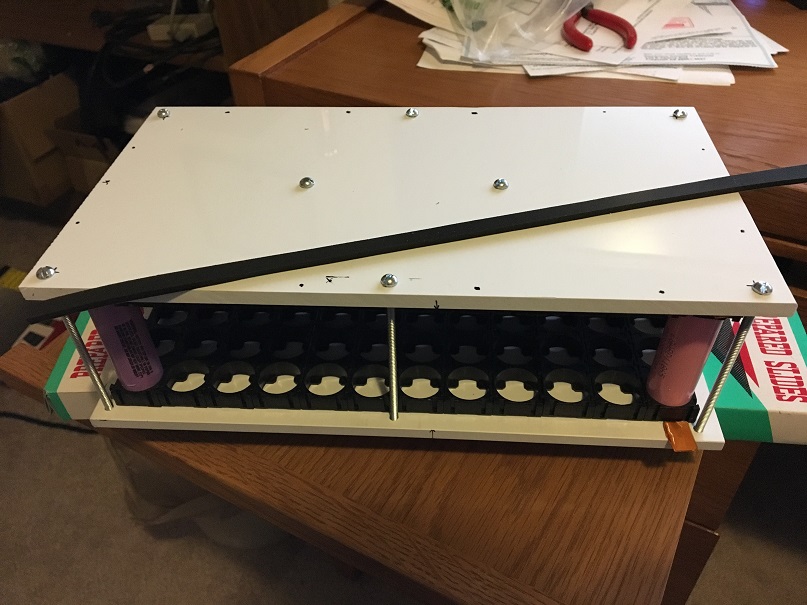
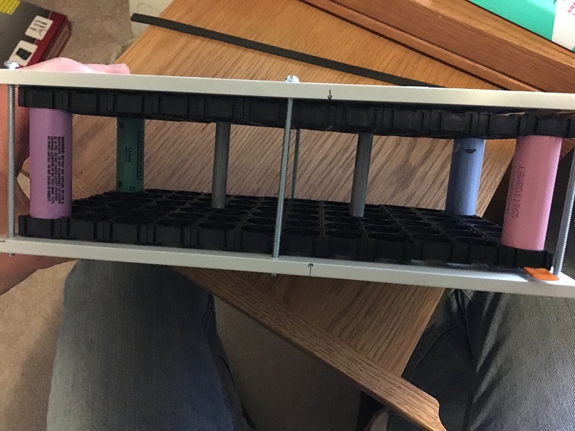
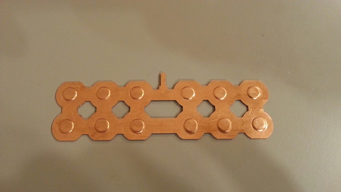
This is a simplified design based off the other solderless packs I've seen here, similar to the one Snath posted here a few years back. The block shown will be 24p3s, going to hopefully build 4 of these which fit flat in my panniers for a 48v motor. The brackets are sandwiched between 1/4" PVC, strips of firm Poron (1 shown on top) will be used to press copper/nickle strips into the cells.

I'm considering keeping the block open for at least some air flow, thoughts on that? Or better to add more rigidity with walls or small strips of PVC alongside the brackets to keep them centered?

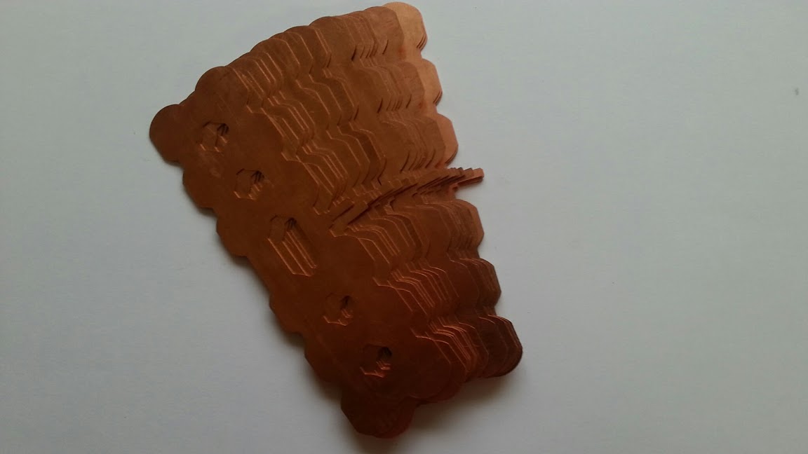
I noticed Snath used copper strips, any issue with using .15mm nickle strips instead?

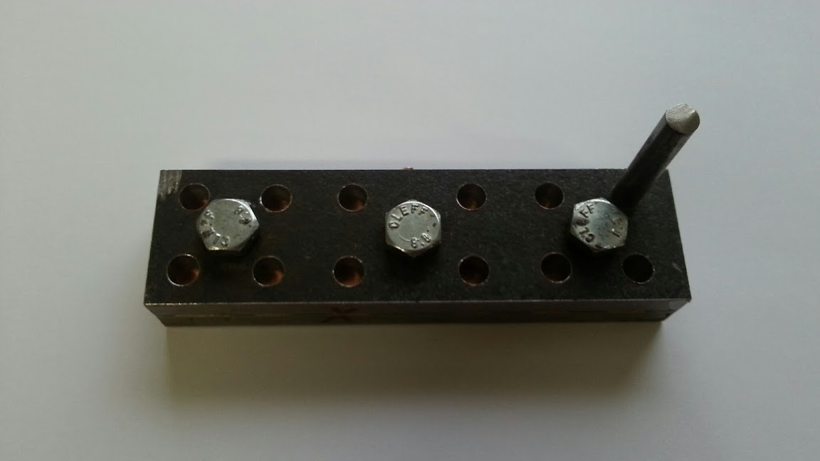
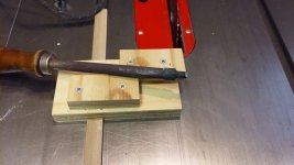
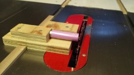
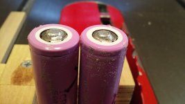
I also need a DIY solution to putting dimples into the strips. I have access to lots of woodworking tools, but no metalworking. I can't think of any clever ways to do this, any ideas?

Looking for feedback, gotchas, improvements, suggestions, etc.

G1nspjW.jpg

hg989UD.jpg
 
The way i did my dimples DIY is i had 2 blocks of 10mm steel and one .7mm sheet. I drilled .7mm sheet and 10mm block clamped together with the right spacing then re-drilled .7mm sheet with larger drill bit (copper sheet thickness x 2 + diameter of previous drill bit)(Important to get it centered second time). You need to sand down/polish the second block smooth to get perfectly even dimple. I used same drill bit for punch. It also has to be square and smooth. If you have a wood lathe, you could get it done. Also drill ant tap to clamp copper in the jig/die. Here is my jig:

upload_-1.jpg


This is before:

upload_-1.jpg


and after punching:

upload_-1.jpg
 
You asked about techniques for making bumps using woodwork tools. Lately, I have been putting solder bumps on the plus end of the cell and using flat copper. I use a table saw to trim the solder to get uniform overall cell lengths. I have not posted this before because some might consider it dangerous and it requires a table saw.

First step: use a very small dab of mild flux on the plus end of the cell (I use Oatey No95 tinned flux). Suspend a gob of molten solder from the your iron. I use Oatey SAFE FLO because it does not contain flux, it is also lead free and appears to me to be more corrosion resistant than other solders. Touch the molten solder to the cell just long enough for the solder to flow out. It cools almost immediately and in my opinion does not transfer enough heat to the cell to cause damage. You may need to add another gob of solder to get enough height, but don't add anymore flux. Here's a photo of the old time iron I use.


Second step is trimming with table saw. You need to make a small sled so all cells can be trimmed to same length. This also allows use of mixed cells which usually have different length tolerances. Here's a photo of this operation. Note that I have removed a bit of wrapper at the negative end so the butt of the cell can contact a flat copper strip.


Here's a photo of the cell after trimming.

I have been using a pack built with cells like this for about 2 months with no problem. I expect over a longer term I will need to check for corrosion. For me it is easier and more accurate this way instead of adding bumps to the copper or nickle sheet. You can see more about my battery builds in one of the links below.
 

Attachments

  • 033 3-8-17 Solder Iron_zpskd5xq4aa.jpg
    033 3-8-17 Solder Iron_zpskd5xq4aa.jpg
    73.4 KB · Views: 972
  • 031 3-8-17 Sled_zps18hknsme.jpg
    031 3-8-17 Sled_zps18hknsme.jpg
    68 KB · Views: 972
  • 032 3-8-17 trimmed cell_zpspp3civzn.jpg
    032 3-8-17 trimmed cell_zpspp3civzn.jpg
    69.3 KB · Views: 972
For those without a table saw or wishing to avoid power tools, a hand-planer could be mounted in the same position the saw blade is, and be used to trim the solder, too.

Might take a bit more finesse but no worries about "oops my hand slipped; I guess that cell has an amp-hour less now". ;)
 
Guys, this design is exactly why use copper with dimple - to avoid heat on cells. Soldering is out of question or IRS better to solder wire strait on the cell.
 
@agniusm:

How did you achieve the cutting of your copper sheets? Did you just press that?

Best
 
Synon said:

Hi Synon, I'm very interested in your fasteners ! Do you have a link to get them? What is the size ? 3.5x100mm ? 3x100?

BTW about battery holders, I'm going to post my grain of salt soon :wink: After I test them above 30A discharge per cell I'll post here. Should interest a lot of people here if these past my own tests as I will be pretty rough on my batteries.

More on topic, there should be no problem with using nickel strips instead of copper. It all depends on what discharge you plan on putting on your cells. You could even try and do cell-fusing wire/strip just like on the topic spinningmagnets posted.

Better not work too much on the 18650 structure, be careful with your tools ! +1 on using Poron foam for killing a bit of vibrations.
 
crud said:
@agniusm:

How did you achieve the cutting of your copper sheets? Did you just press that?

Best

Many options these days. Waterjet, laser, stamping. Depends on quantities you need
 
Back
Top