Current Mod for Meanwell HRP-450-24

EDS

10 mW
Joined
Jan 9, 2011
Messages
22
Location
Colorado
I have several of these power supplies in my junk pile, so I would like to do the "R33" type mod to drop the current, as described here:
http://www.recumbents.com/WISIL/e-bent/meanwell/default.htm

I've spent a while looking at similar conversions, but have not found info for this particular model (very little info about the HRP series). If I get it done, I would be happy to do a writeup for the wiki. Can anyone direct me to a link to someone hacking something very close, or a nice writeup for how to find the relevant resistors on an unknown power supply? I understand the concept of using a pot to alter the voltage divider, but hacking without a schematic is a stretch for me.

They seem to be nice supplies. They have built in over-current protection, so they should be hackable.
MW HRP-450-24 Block Diagram.JPG

I plan to use 2 in series to bulk charge 12s 16Ahr Multistars. The supplies put out much more current than I need (18.8A), but they are what I have in the pile, so I'd like to use them.

The supplies also have voltage correction. I think this is managed by the daughter board shown below. Not sure if current control is managed on the same board.
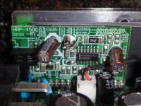
MW HRP-450-24 Daughter Board, compressed.jpg

Thank you.

Link to datasheet:
http://www.mouser.com/ds/2/260/HRP-450-SPEC-806168.pdf


The daughter board is located at the circled area.
 
Yes it would be nice to limit the current. I bought some of Teslanv's HRP-300-24 and would like to lower the current.
I may just buy fetchers board.
https://endless-sphere.com/forums/viewtopic.php?f=31&t=68195&hilit=hrp+current&start=75#p1114640
https://endless-sphere.com/forums/viewtopic.php?f=31&t=36958&hilit=fetcher+current+limiter#p536854
https://endless-sphere.com/w/index.php/S-350-36#Restricting_Current_.28Amps.29:
Build your own fetcher current limiter - Does not look hard at all. Bread board and some components.
https://endless-sphere.com/forums/viewtopic.php?f=31&t=21768#p317151
I may do it that way.
 
Thanks for the information. I'll search for DrAngle. I had looked for Fetcher's limiter, but the boards are long gone. Could breadboard it, but it makes so much more sense to simply add one pot to the existing circuit. Assuming the relevant circuit is near the output terminals, there aren't many components in that area, so I may be able to figure it out.

I think if the output is connected to a lab supply set near the nominal voltage, it will power the relevant circuits, including the IC's. This allows you to probe voltages without AC power connected. There are instructions for doing this to change the output voltage of a non-adjustable PS. The procedure is probably similar for current adjustment, but maybe harder. For voltage, you can simply ramp the voltage on the lab supply above and below the nominal voltage of the power supply, find the pin that toggles off and on, and use that to track down the voltage divider circuit. It's not as easy to manipulate and measure current, especially without AC connected.

I think I will stick a cheap CC/CV driver on it for now, until I find time to investigate the circuit. This should work fine for trickle charging, so I don't need to split the pack every night to put it on the hobby charger, and I won't need to manually precharge the caps before remaking the connection since I can keep it all connected and charge through a parallel cable I wired in. It would waste most of the power capability though. The two Meanwells can put out 900W, but the cheap drivers only seem to be available up to a few amps.

I was nervous about using a cheap generic driver with a big lithium left unattended, but since I don't charge all the way, the risk of overcharging seems low. If the Meanwells are set to 50.4V, and the driver is buck only, the driver should be able to get the final battery voltage within a volt or so of that, which is where I normally finish anyway. If the driver malfunctions, it will still only charge to 50.4V.
 
I'd like to add a pot for my hrp's as well. I guess you'd only have to limit one in the series- but so far all the farther I got is thinking I'd just just series in my lab supply, since that works between 0-10a and I found no simple cheaper products or mods.

I think if the output is connected to a lab supply set near the nominal voltage, it will power the relevant circuits, including the IC's. This allows you to probe voltages without AC power connected. There are instructions for doing this to change the output voltage of a non-adjustable PS. The procedure is probably similar for current adjustment, but maybe harder. For voltage, you can simply ramp the voltage on the lab supply above and below the nominal voltage of the power supply, find the pin that toggles off and on, and use that to track down the voltage divider circuit. It's not as easy to manipulate and measure current, especially without AC connected.
Interesting stuff. Please post if you find anything in those huge meanwell threads, or figure it out!
 
What would an appropriate pot size be to alligator clip in parallel. I gotta pretty good idea what the resistor may be, its just a guess on my part. I got some mega ohm pots, but I dont want to randomly place in parallel, I will have to research it a bit more, based on other threads, such as DrkAngel's.
 
For pot size, I'm not an expert, but this is what I think would work.
Try to read the text (if SMT) or bands (if thru hole) to find the value of the resistor you are planning to put the pot in parallel with. Measuring it in-situ may not be accurate, b/c it may be connected to other things in parallel. The text is not the value in Ohms; it is in code. Explanation:
http://www.instructables.com/id/Reading-Surface-Mount-Resistor-codes/

If you can't get a reading on the resistor, hopefully there is another reference. If not, a good guess would be a few hundred, up to ~10k Ohms.

For the high-resistance pot setting:
If you parallel a pot much larger than the resistor (>= 10x higher resistance), then it will not change the circuit very much so it seems safe.

For the low resistance pot setting:
Somewhere on the order of the same resistance as the resistor in parallel, possibly down all the way to zero ohms. If you parallel the same resistance as the original resistor, the circuit will act as though the original resistor were half the value it is. This should be plenty of change to observe a significant effect. Zero ohms would basically short out the original resistor, obtaining the maximum effect possible from this version of the mod.

A mega Ohm pot would probably be safe, but may not go low enough to observe much change. Even if it does, it may be twitchy at the low end since the adjustment will be coarse. If it's a multi-turn pot, & it goes down to around 100 Ohms or less, then it could work well. If you hook it up with it set to the max Ohms settings, then slowly turn it down while observing the effects, then you may figure it out. That is if you have found the correct resistor. I really don't know what it would do if you short out some other resistor on the board. Thanks for trying. Please report back how it goes. I probably won't get around to trying anything for at least a week.
 
That's some good info. If I had more than 50% hope I could pull it off without wrecking something I'd give it a shot. Somebody's gonna have to go before me though lol.

Btw I did try adding a lab supply, but it could only start at it's max capacity without hitting OC protection. From there I could turn it down gradually, but that won't work for my purpose of using a little inverter or genny to power it. Post 8 https://endless-sphere.com/forums/viewtopic.php?f=1&t=87821 Will just spend the 100$ for a lighter 'travel' charger and spare.
 
I think I have a good idea how to figure it out.

I originally thought the overcurrent circuit would be on the main board, near the output terminals, but there aren't many components there at all. There's a thru-hole resistor labeled L151 (which I don't understand since that looks like an inductor designation). There's something labeled RG1. I thought that may mean "gain resistor", which could be relevant, but it has three pins and is heatsinked, so I don't understand that one either. Maybe the markings refer to something on the other side of the board (haven't taken it out yet). The only other resistor on the board is probably a thermistor.

Now I think the circuit is probably on the daughterboard (pic in first post). There are several resistors on the daughterboard. I looked up the main chip on the daughterboard. It is a TI LM324, which is a 4-channel op amp. Link to datasheet:
http://www.ti.com/lit/ds/symlink/lm2902-n.pdf

The PS has four different protection / correction functions: 1. Overcurrent 2. Overvoltage 3. Over Temp 4. Compensation for voltage drop in the power cables.
All four functions could be handled by that same chip.

So to test:
- The LM324 has four pins which are outputs. Look up which ones they are on the datasheet.
- Hook up a load which will send the supply into overcurrent protection mode.
- Probe each of the four output pins, while connecting / disconnecting the load. Find which pin changes when the supply goes into overcurrent protection mode. That pin is on the channel which has the relevant voltage divider circuit. Check the datasheet to see which pins are the inputs associated with that channel (there are only two input pins per channel). Follow the traces on the board to see what resistors are connected.

That seems like it would get pretty close. I don't know when I'll get around to testing it. I just thought of this on my lunch hour. If anyone tries it or knows that this is wrong for some reason, please post. Thanks.
 
Back
Top