Shunting power between packs Ideas.

peterperkins

100 W
Joined
Jun 6, 2008
Messages
196
Lets assume we have two 180V ish battery packs A & B that we want to connect in parallel but in a controlled fashion.
They won't always be at the same voltage and I want to control; the power flow back and forth between them as they fluctuate.

A will sometimes be higher than B by say upto 50V and vice versa.
I want about 10-20A bi-directional current flow pwm controlled max between them independently controlled.

I was thinking two discrete IGBT'S paralleled in reverse inserted into the + line ..
Each controlled by an isolated pwm driver.

The potential difference between the packs would help control the current flow.
The independent pwm for each direction could be set as the ultimate current limit at the maximum pack voltage disparity.

So one IGBT controls flow when A is higher V than B and the other when B is higher V than A...

Make sense? Any nightmare issues?
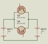
PackFlow.jpg
 
peterperkins said:
A will sometimes be higher than B by say upto 50V and vice versa.
I want about 10-20A bi-directional current flow pwm controlled max between them independently controlled. . . .

Make sense? Any nightmare issues?

50V, 20A = 1000 watts.

You really want to dissipate 1000 watts in those IGBT's?
 
peterperkins said:
Lets assume we have two 180V ish battery packs A & B that we want to connect in parallel but in a controlled fashion.
They won't always be at the same voltage and I want to control; the power flow back and forth between them as they fluctuate.

A will sometimes be higher than B by say upto 50V and vice versa.....

once they are connected in parallel, why won't they always be at the same voltage ?
 
craigsj said:
Nothing limits current once a switch is turned on. You have two states, off and fireball.


Well put.

A single IGBT/FET/SiC switch and an inductor between the two with current instrumentation fed to a micro controller running the gate driver to the switch would enable making the bucking DC-DC you're looking for. At this low of a power level though, just using the pack you want to transfer energy from to power a couple kW charger to charge the lower pack is perhaps the lowest time/cost solution.
 
Thanks for the comments. OK a few more details.. This is a Honda Insight MK1 project.

Pack A is 50S Lithium supercaps. It's operating range is 110-190V (3.8v per cap max)
Pack B is 50S (7-8 year old) A123 pouch 20ah cells. Highish IR. It's operating range is 110-180V approx. (3.6v per cell max)

I do not want them permanently connected together at this stage. I may try that later..

Pack A provides the power for the car IMA hybrid system. I have run that successfully for several thousand miles..
It's voltage goes up and down rapidly in response to demand/regen etc. No issue with that. It doesnt have that much capacity..

http://www.insightcentral.net/forums/modifications-technical-issues/17282-super-capacitors.html

However I want to add the old A123 pack to provide the 'capacity' and set the pwm link between them to continuously charge the supercaps at a set rate say 10-20A which they can cope with.

So let's say Pack A is at a lower voltage than Pack B. System detects this and turns on PWM (B to A) and charges pack A until they match voltage of B.
As the pack voltage gap diminishes then with a fixed pwm say 5khz 50% duty the current will fall naturally as they merge..

Vice versa also applies, if regen pushes the supercaps Pack A voltage up above Pack B I may want to bleed off charge back into the A123 pack via the reverse IGBT (A to B) This bleed off would continue until the voltages match as above..

Pack and system IR would also help to limit current.

If they were connected directly together then yes that would be interesting, but I want to protect the old A123 pack from high current demand and minimise the peukert effect.. So i don't want the IMA trying to pull 100A out of them... A constant charge of say 10A from the A123 to the supercaps would keep the caps up and minimise voltage sag in the A123 pack allowing more energy to be extracted from them and transferred to the supercaps.


Note the IGBT's in my schematic were just random ones chosen to illustrate the idea.
Obviously I will keep the final IGBT's within their safe operating windows...
What switching frequency do you recommend?
The link between the two packs will also be correctly DC fused.
 
Yeah, I see what you're trying to do and it seems like it could be made to work, but it also seems like you're babying those A123 cells a bit ;)
 
Back
Top