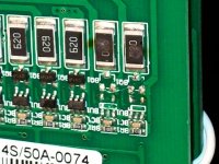
Failed Besttech BMS bleed transistor, how to disable?

vex_zg

100 W
Joined
Mar 6, 2016
Messages
178
Hi all,

I have this BMS Besttech HCX-D131
http://www.bestechpower.com/592v16spcmbmspcbforli-ionli-polymerbatterypack/PCM-D131.html

one of the bleeding transistors has failed and is continuously draining one cell group (first group). Fortunately I was checking voltages and caught this failure in time.

I remember seeing some pics on the forum how to lift off the balancing transistor but can't find it now.

I would like to keep the low voltage protection/detection but disable the bleeding/balancing.

anybody have advice how to do it?
 
You need to find the balancing drain resistor that goes to the cell in question. There should be a transistor that connects directly to it. I had one do that and I just used small wire cutters to snip the legs off the bad parts. There is typically a voltage detector that drives the transistor, which is probably the part that actually failed. Snip that off too. The HVC and LVC still work, just not the balancing function.

You may need to manually balance the cells that got drained by the bad channel.

My theory is these things blow up when the balance connector is attached. The transistor and voltage detector chip have a maximum voltage rating of around 12v. When everything is connected, this is fine. When first making the connection to the pack, if wires from the positive end of the pack make contact first, you can get a string of shunt circuits in series powered only at the ends. Due to variations in the capacitor values, one or more shunts may come on, dropping the voltage to near zero for that shunt, which causes the slower ones to get more than their rated voltage and blow up. The trick is to try making the negative most cells connect first by angling the plug when attaching.

Of course there could just be crappy quality parts that failed for no good reason.

BMS toast1.jpg
 
thanks for the info!

Yeah, I think the failure actually occured when I was reconnecting the BMS.

I wonder would the LVC per cell still work if I do this mod or just the overall LVC for entire pack? I have no use for overall LVC since I monitor pack voltage anyway on my LCD.
 
There are lots of variations in BMS design, but most of the typical ones have a separate voltage detector for the balancing shunts that won't affect the LVC and HVC. Those should still work like before. You should check balance once in a while to make sure those cells stay in line. You can manually balance if needed.
 
fechter said:
There are lots of variations in BMS design, but most of the typical ones have a separate voltage detector for the balancing shunts that won't affect the LVC and HVC. Those should still work like before. You should check balance once in a while to make sure those cells stay in line. You can manually balance if needed.

I just swapped/resoldered some of the parts between channels, to see if I can pinpoint which ones are faulty
But the entire bms has been painted over with some material that acts like glue once heated with hot solder and is non conducting, making any troubleshooting difficult - not possible to check anything using multimeter unless the,goo is scraped away.

I think I will go adaptto with BMS. That appears to be the cleanest solution integrated with the display. The controller is extremely pricey though.
 
I just would not let it go

yes you are right it was one of the voltage detection transistors I assume, some are labeled GCLR and some GCLQ . I can't get any datasheet or replacement part on them, so I just lifted that one away. I'm thinking to add LED diodes for all balance circuits to be able to see when balancing is taking place. The balancing is done with 4 resistors of 100 Ohm in parallel, and it does get warm/hot even with just this one channel that was getting contiously drained. I imagine the board would get quite hot once most of the channels would be getting balanced.

on the image below it is the circled element:


edit: this failed element labeled GCLR and GCLQ has been discussed already in this thread, it's a Lithium cell protection IC

https://endless-sphere.com/forums/viewtopic.php?t=87134
 
so, even though that GLCQ IC failed, it is also needed to remove the transistor below it, see picture:


When I had tested the BMS After removing only the 6 pin IC marked GCLQ (and leaving the 3 pin transistor in place), still some drain current was happening, probably because the gate or base of the transistor was floating and not pulled up/down.
 
vex_zg said:
When I had tested the BMS After removing only the 6 pin IC marked GCLQ (and leaving the 3 pin transistor in place), still some drain current was happening, probably because the gate or base of the transistor was floating and not pulled up/down.

I found the same thing. You'll notice in my picture both parts are gone.
 
Back
Top