Dissected my Jetson 48V Battery -- power cutting out.

Telemachus

10 W
Joined
Jul 15, 2013
Messages
99
Location
Riverside, CA
I got a Jetson scooter/e-bike used 2 days ago. It's fun to ride, but I'm only getting about 8 miles before it turns off. The power just cuts off, especially if going up hill. I can open up the seat, turn the main power switch on and off, and then go another 100 yards until it cuts off again.

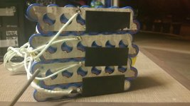
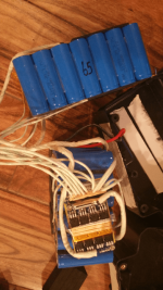
I opened up the battery tonight after the bike would go no longer to to check out the cells.

91 x 22650 cells, arranged in 13 groups of 7.

Each array measures 3.88-3.91V.

I am going to charge it overnight and see what they measure fully charged. I can also hook up the voltmeter to the battery terminals to see how low the voltage goes while running, but my guess is I am dropping below the minimum voltage since the display on the bike goes to one bar before it cuts off.

Is it more likely the controller shutting off power or the battery control system? Or are those just doing their job, and the battery is bad?
 

Attachments

  • 2017-08-18 21.50.24.png
    2017-08-18 21.50.24.png
    131.1 KB · Views: 3,253
After charging, all arrays were at 4.18-4.19V except for one at 4.08. I removed the connector from the BMS and plugged two jumper wires into that array to hook up to the hobby king charger. I figure I will charge all of them individually to get to 4.2 and see how the balance holds over the next few cycles. So far, it seems like all of the cells are fairly good, although I cannot test them individually.

Either the BMS or speed controller is cutting power when each cell is at 3.88. I'd much rather go to 3.6/3.7.

Can someone give me a recommendation of what the next step is? Hook multimeter to battery and see what the voltage actually drops to while riding?
 
maby these cells are so old and bad that they drop down under maximum load?bms see 3volt on the bad cell and cut of the power :idea:
 
Unfortunately it's pretty challenging to measure the voltages on anything while riding. A test load with about the same current draw would be a lot easier but most people don't have one lying around. I've used a hair dryer before.

A weak cell group might measure OK when not charging or discharging. You could run the pack down to about half charge and measure the individual cell voltages. Then connect the charger and measure again, looking for one that jumped up more than the others. This would indicate a weak group.

Another test is to run it until it cuts off like before, then measure the voltage on the pack without turning anything off or unplugging anything. If there is still voltage, then it's the controller. If no voltage, it's the pack BMS.
 
I'm not quite sure how I could check the voltage without unplugging anything...

But when the battery died this last time, I pulled it out of the bike and tested it. The pack in its entirety was at 50V with about 3.88 per array.

The bike has a 500W motor. Are you suggesting a 500 watt hair dryer? Plug the main AC leads into the battery??
 
fechter said:
Unfortunately it's pretty challenging to measure the voltages on anything while riding.
If no test load is available, flip the bike upside down or otherwise set it up so the motor wheel is offground. Use the brakes lightly to simulate various loads.

Yeah, it'll wear out pads if you do it a lot but if you just need a quick stationary load test it works great. ;)


Usually the plugs on things have open backs where the wires go in, and you can often reach the back of the contacts with the meter probes.

If not, then if the individual power wires are accessible you can push pointy meter probes into the insulation on the wires to contact the wire inside, or use needles, etc, and touch the probe wires to those.
 
So basically, whatever it takes, drain the (now balanced) battery enough to see if any of the arrays are out of balance. Then, charge for a set amount of time and measure how many volts went into each array? If one took more volts that the others, assume the capacity of that array is bad, and further investigate the cells in that array?

I already have one array of 7 that is suspect. Even after several hours on the hobby charger, it won't get to 4.2V
 
measure the cell group voltages while it is draining.

put the voltmeter across each cell group's +/-, then put the load on the battery while watching that group's voltage. Note down both before and after voltages.

Take load off, move meter to next group, retest, note down both votlages.

repeat until all groups are measured with and without load.

The ones with the biggest difference between unloaded and loaded are the ones with the worst internal resistance / lowest capacity / etc.
 
Makes sense. I think I'll use a few 100W incandescent's in series and start taking measurements.

With a battery of unknown age (and history) is it likely that it could be just a few bad individual cells pulling the whole thing down?

In other words, if I can isolate a bad array, and separate and check the cells individually, is there a chance I can pull the whole battery back with just a few replaced cells?
 
There is a chance you can at least get some more use out of it. If the cells were all matched to start with and never abused, expect them to all fail around the same time. In other words, don't expect miracles.
 
Telemachus said:
I think I'll use a few 100W incandescent's in series and start taking measurements.
You'll need to put them in parallel, not series.


With a battery of unknown age (and history) is it likely that it could be just a few bad individual cells pulling the whole thing down?

In other words, if I can isolate a bad array, and separate and check the cells individually, is there a chance I can pull the whole battery back with just a few replaced cells?
Possibly, though you may have to replace the groups they're in rather than just the cells. And as Fechter notes above, it's not going to make the pack new--it's just going to improve it by the margin of the other existing cells.

If you search my posts for the Vpower / CammyCC pack repair threads, you can see some of my testing/repair procedures. There are also hundreds of other battery repair threads here on ES, if you look around, that will show other methods for other types of packs.
 
Thank you. While not a novice to electronics, I am for sure a newb with e-bikes and non-lipo batteries.

I figured my first step was testing the finding the problem, and then diving into how to repair them. I have already read quite a bit about matching cells and spot welding the cells. BMS and wiring all seems pretty straight forward.

I ran a single 100W light bulb off the battery for about 30 minutes. All of the arrays dropped .03-.04V. I'm not sure if that is a heavy enough load to strain/test the battery. I could parallel 2-3 of them if needed.

The only hair dryer I have is 1800W. Not sure that is a good idea.
 
After discharging and recharging all of the cells, it seemed like all cells discharged and charged evenly. 4.19-4.21V on every array. 54.6V fully charged. I threw it in the bike today and it did great for the first mile. Then on a slight incline the battery meter dropped to 2 bars and it cut out. I had to turn of the main power and turn it back on. Then I was able to go until the next incline and the same thing would happen

After 5 miles and about 8 resets, I measured the battery at 52.1V. Flat road is fine but even the slightest climb will kill the power.

I'm back to either the BMS or controller cutting power. Not quite sure what the next step is. I would imagine I need another battery to test it against.
 
Telemachus said:
After discharging and recharging all of the cells, it seemed like all cells discharged and charged evenly.
So none of the cells dropped in voltage with the load connected vs with it not connected, at any point during the discharge? (the load has to be high enough to simulate the load seen by the battery and bike when it shuts down. if it is not hgih enough the problem won't happen and you may not be able to detect it).

I ask because that is the test that has to be done to eliminate the cells as the source of the problem (which would cause the BMS to do it's job and shut down to preserve the pack from damage). It is a test that would simulate the failure you saw in the on-bike test.

It would be more reliable to do this test with the actual bike, wheel off ground, using the mechanical brakes to momentarily load the wheel/motor during the voltage readings on each cell. That would produce a load more like what the bike actually experiences, and be more likely to show you a problem by the voltage drop.

If you also have ebrake switches in the levers you can unplug them temporarily to do the test, so tehy don't shut the motor down while still engaging the mechanical brake on the motor wheel.


If there is no problem detected on the cells themselves, there are other parts to test that can be done this way. (measure voltage across connectors for battery or phase wires, to detect a poor connection).


A 100w bulb won't draw 100w from that pack; it's not high enough voltage. You can measure the current actually drawn, but i doubt it's enough to simulate the load the problem is caused by.
 
I really appreciate your help with this (and just sent a few bucks your way to show it).

I took a ride out again, so got just under 10 miles today. By the end, I was resetting the controller every 200 feet to get home. Ended at an even 48V.

So based on your suggestion here is my new plan:
1) Open up the charged battery to see the cells.
2) Hook it up to the bike.
3) Disconnect the break cutoff, bungy the break enough to give some resistance, tape the throttle in the on position.
4) Measure the voltage across each of the arrays over time, and look for any that seem to drop significantly.
5) Report back

Of note, the speed controller says it has a voltage cutoff of 40V. Even if one whole array were removed, I wouldn't be anywhere near 40V... another thought I have had is to connect 4x3s 2200mah 40C Lipos that I have in series and run the motor (or ride it) until they are at 3.7V per cell. If that powers the thing fine, without any cutoffs then I could eliminate the controller as the problem.
 
Telemachus said:
I really appreciate your help with this (and just sent a few bucks your way to show it).
You're welcome, and Thanks! Every penny helps...partly to feed the monsters, Kirin and Yogi:
file.php

file.php

file.php

and partly for the rest of the household budget, and on the rare occasion something is leftover, bike stuff. :)


So based on your suggestion here is my new plan:
1) Open up the charged battery to see the cells.
2) Hook it up to the bike.
3) Disconnect the break cutoff, bungy the break enough to give some resistance, tape the throttle in the on position.
4) Measure the voltage across each of the arrays over time, and look for any that seem to drop significantly.
5) Report back

Step 3 and 4 should be a a little different so you can see the voltage under momentary load and with no load. This can be important so that you can watch the cells drop in voltage. Only those that drop a lot more than others are really the problem, assuming that some do that. Typically this will show a problem at any state of charge, though it's often more exaggerated as it gets closer to empty.

So I'd not bungee the brake, but only engage it for a moment while watching the voltage reading on a cell (group). Then move onto the next group and repeat.

To connect to the cells, you can use alligator clips on the meter leads, and either insulated sewing needles, or some stiff insulated wire like CAT-5, to insert into the balance connector from the back (where the wires enter), or a similar arrangement.


Of note, the speed controller says it has a voltage cutoff of 40V. Even if one whole array were removed, I wouldn't be anywhere near 40V... another thought I have had is to connect 4x3s 2200mah 40C Lipos that I have in series and run the motor (or ride it) until they are at 3.7V per cell. If that powers the thing fine, without any cutoffs then I could eliminate the controller as the problem.
It's most likely the battery, so this test will probably pass. :)
 
Pass it did.

I soldered together a cable and ran those little lipos until they were at 3.7V per cell. (About 15 minutes.)

Although with 12S, it was not as peppy as the fully charged 13S stock battery, and hills were a challenge (had to pedal a few times to make it up), I never lost power, despite headlights being on the whole time.

The lipos were a little warm, but nothing like how hot they are after 4 minutes in a 3D 500 helicopter with 100% headspeed.

So it's got to be the BMS cutting power... more testing of the individual cells to come...
 
You want to be careful that none of the cells are dropping down to the danger level under load. If a cell goes below about 3v under heavy load, it will probably puff and be permanently damaged.

If none of the cells are actually dropping below 3.0v or whatever the cutoff is set at, then the BMS might be tripping due to over current being sensed. Typical cheap BMS board will have a current measuring shunt made from heavy Manganin wire or surface mount resistors. The trip point can be increased by decreasing the sensing resistor value.
 
Thanks fetcher.

No puffy on Lipos, but they weren't really a long term solution, just a way to eliminate the controller as the problem.

My guess with what I have seen with the cells on the stock battery is that the BMS is the problem, and the cells are good. I still need to confirm that.

I am going to ride the bike until it cuts out and then try reproduce the problem in the garage by using the brakes on the kickstand. I'll hook the probes up to the back of each individual cell group plugged into the BMS and see what voltage they go to before it cuts out.

I have a hunch that it has been problematic since the beginning, as I am at least the 3rd owner of this bike... previous two probably knew there was a problem but realized it didn't pop up until about 5 miles into a charged battery so were able to shuffle it along and feign ignorance.

But I'm determined, thus bike is gunna work for me. :lol:

Is there any practical way to tell what the LV cutoff is on any given BMS?
 
Using the brake to load the motor while measuring is good. Just keep an eye on brake temp. I've seen plenty of cells that measure fine at rest but sag like crazy under load, which can trip the low voltage cutoff.

Most of the boards I've tested cut off at 3.0v. In theory, you could read the markings on the chips and tell from that, but finding the right datasheet is hard.
I have a bench test setup with a variable power supply and a battery pack simulator made of a string of resistors. I can vary the voltage and monitor the signals going to the charge and discharge control FETs.
 
I honestly think I'd rather it be the BMS then a bad bunch of cells. 22650 at 2500mah are pretty costly. I wish the battery was built on 18650.

BMS appear to be fairly cheap and omnipresent on ebay/amazon!
 
Telemachus said:
My guess with what I have seen with the cells on the stock battery is that the BMS is the problem, and the cells are good.
It's unlikely that the BMS is bad. The failures of bad BMS are typically:
--draining down a bank of cells constantly due to stuck-on balancing circuit
--not allowing either (or both) charge or discharge due to failed input or output FETs

Early LVC, or shutdown under load, isn't usually a BMS failure. It's almost always cells. Occasionally it's a balance wire with a bad connection between the cell group and the BMS.

I don't know what your BMS's LVC is, but personally I'd prefer an LVC of around 3.5v, maybe 3.3, to keep cells from going down too far--it does mean that you don't get every drop of capacity but it also means the cells aren't run down as hard so they last longer. :)
 
I think I found the culprit. The row with the marked blue star dips well below 3V whereas all the others never get below 3.3.

According to my voltmeter, LVC on this BMS is 2.8. Each time that cell hits 2.8 the whole power cuts off. Several others got down to 3.3. Maybe that's why this cell is toast!

All of the cells are at about 3.6 right now except that one culprit is 3.45 resting.

I figure I will charge the whole battery back up and see where that one stops. Then I can hook that cell to the hobby charger to see if I can get it back in balance... but my previous testing up until now shows that they all make it to 4.2.

Or should I leave it discharged in preparation for removal of that array?

Since I know that the bike runs on 12S (from my lipo testing) I could snip the nickel connections to that array and resolder the BMS leads to bypass it... if the bike runs without cutting out then I know what the next step is... replace that array.

Suggestions Maesteos?
 

Attachments

  • 2017-08-22 23.28.15.jpg
    2017-08-22 23.28.15.jpg
    211.7 KB · Views: 3,101
Telemachus said:
I think I found the culprit. The row with the marked blue star dips well below 3V whereas all the others never get below 3.3.
That's exactly the kind of thing I'd expected.


According to my voltmeter, LVC on this BMS is 2.8. Each time that cell hits 2.8 the whole power cuts off. Several others got down to 3.3. Maybe that's why this cell is toast!
2.8V LVC is way too low for non-LiFePO4 cells. Since the cells charge to 4.2v either they are being overcharged (for LiFePO4) or they are non-LFP cells and are being overdischarged due to the too-low LVC.


All of the cells are at about 3.6 right now except that one culprit is 3.45 resting.
That would be around full charge for LiFePO4, and pretty low for other Li types.


Or should I leave it discharged in preparation for removal of that array?
If you're going to be disassembling things, it's safer to be working on at a lower state of charge in case of accidental shorts. ;)

But it's easier to rebalance with everything already charged up, so you can just install the already-charged new array, too, and off you go.

So I guess it depends what you feel comfortable with.


Since I know that the bike runs on 12S (from my lipo testing) I could snip the nickel connections to that array and resolder the BMS leads to bypass it... if the bike runs without cutting out then I know what the next step is... replace that array.
It's possible the BMS will not operate at all without all the balance leads connected to a voltage that is above it's LVC. (it shouldn't, if it's properly designed--unfortunately most are not).

If it does, then it means it's not designed to detect a zero-volt cell, which means it could potentially allow a disastrous situation to occur, where a cell group that's internally shorted so it's discharged itself will then still pass charging current, but may heat excessively inside and depending on how hot they get could ignite and cause a full-on battery fire.

Not a likely scenario...but a possible one.

If you want to try removing that group, I'd recommend disconnecting the entire BMS first. Start at the main +, then each of the wires to the cells, starting at most positive, working down to the one on the bad group. After those are all removed, you can leave the BMS negative and any other cells more negative than the bad group in place.

When you reconnect, start at the most negative end and work your way up, leaving the most positive balance lead taped off and unconnected, and then connect the main pack +.
 
Back
Top