Serial connection for 2x 36v BMS batteries?

eisaiasjr

1 µW
Joined
Sep 6, 2017
Messages
4
Hello,

I recently bought an ebay deal that has 10x 36v battery packs (10s2p). Link below...

http://www.ebay.com/itm/like/172648854096?chn=ps&dispItem=1

and I am wondering if I can connect 2 of these in serial to effectively make a 72v pack... or if it just blow the BMS?

Your response is appreciated!

E
 
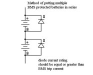
It can work if you add a large diode across each pack (reverse biased). Normally it's no problem, but if one pack decides to trip for low voltage or over current, the full voltage of both packs would be across the FETs, possibly blowing the BMS. With a diode across each pack, if one trips, only the single pack voltage (plus about 1v drop from the diode) will be across the FETs, so no smoke.

BMS in series config.jpg

That's not a very big pack. What are you going to power with it?
 
fechter, would the diodes be necessary in a series/parallel arrangement? It seems to me that the parallel modules would safeguard the others...

eisaiasjr, we may be attempting the same thing... do you intend on putting five of those modules in parallel, in series with another bank of five in parallel? Maybe we can work together on this? I don't want to hijack your thread... let me know if you'd like me to frock off :D otherwise, maybe I can share what I've found.

I've got one of the packs in my hands and I'm experiencing what others have... that they're great packs and are close to what is advertised in the auction. I've heard there may be inconsistencies with BMS mounting and/or type of connector... will you please let me know if you come across any issues?

If you're wanting to use all ten modules, configured for 72V, have you sourced a charger yet? I had a ton of difficulty finding inexpensive 72V chargers at the power level that we need. To accommodate a much easier to deal with voltage of 36V, I am considering using a relay and two diodes to change the configuration of the pack, for charging only. The relay+diodes will reconfigure the pack from the original 5+5, to putting all ten of the "alarmhookup modules" parallel. Naturally, it seems that the doubled charging current requirement has now made things difficult again :roll: A possible solution might be to use a "Turnigy Reaktor" or a "Charsoon Antimatter" Li-ion balancer (120USD) and feed it with a cheap switching power supply that I've yet to source.

In case it's useful to you, here is what I came up for voltages/currents according to the datasheet, for the final configuration of 72V and ten modules. Neither my target values for charging current (design), nor my mathematics has been independently verified.

My definitions:
Cell = A single 18650
Module = The 10S2P, 36V @ 4.4AH with BMS from Ebay seller "alarmhookup".
Wholebatt = The entire battery, configured as 72V (20S) 20AH (10P) for a stored energy of 1.44kWH (1440 watt/hours). I've intentionally rounded the 4.4AH to 4.0AH.

Normal charging currents, extrapolated from datasheet:
Cell I_charge_normal: 0.5C (1.075A)
Module I_charge_normal: 2.15A
Wholebatt I_charge_normal: 10.75A <----- This is a good starting value for what the charger should supply

Maximum charging currents, extrapolated from datasheet:
Cell I_charge_max: 1C (2.15A)
Module I_charge_max: 4.3A
Wholebatt I_charge_max: 21.5A

If I can't find a cheap 72V 10A charger, [EDIT: Why not three of THESE in parallel?!] the schematic shows the circuit I plan to use to re-configure the pack to 36V. I sourced some really good diodes... they'll hardly affect (0.6V or less) the final charge voltage. The schematic is lacking the circuit to detect the presence of the charger, I haven't "designed" it yet but it will be simple. Probably just a single BJT transistor across the front-end. When the charger is applied, 36V will appear, turning on the transistor, which turns on the contactor coil, opening the contacts. (Only the contactor's N.C./Normally Closed contacts will be used.).
 
Not at all!

Great information on this thread. I am sure many people are thinking about the same thing....
 
Pyrotrons said:
fechter, would the diodes be necessary in a series/parallel arrangement? It seems to me that the parallel modules would safeguard the others...

Well, that would be true of only one pack tripped, but what could easily happen is once a pack trips, it places too much load on the other parallel pack and it trips right away. I would place the reverse diodes across each series unit just as cheap insurance.

I like your clever series/parallel switching arrangement. The charging voltage would need to be increased slightly to compensate for the diode drop but this should be pretty constant.
 
A few of things about this pack...

Unlike the original description on eBay... It's NOT a high season pack capable of 10A per cell. Instead, the LG specs show a continuous discharge of 2C (4.4A).

Care must be taken when used in high drain implementation like an e-bike...

Each pack is capable of 8.8A continuous, so you must parallel a few packs of you need more power...

I am planning on doing the exact same implementation as you... 2S5P for a 72v ebike
 
LG cells were only 2C?
[strike]What labels, ID on the cells.[/strike] ICRMF11865 = ICR18650 MF1

Samsung version, from same seller were Samsung ICR18650-22p rated at 10A continuous, 20A surge per 2.2Ah cell = 4.5C & 9C.

Also now offering batteries with Sona high output cells.
 
From old thread
Found a ...
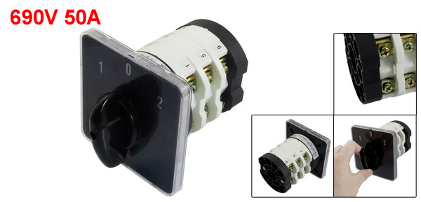
12s2p >>> 6s4p switch with full redirect for 12s controller and 6s charger

690V 50A 12 Terminals 3 Positions Rotary Cam Changeover Switch $25.98 +$5 shipping

new link


660V 125A changover switch - $40.89 shipped

and mapped for Series - parallel switching

file.php


1st position enables
1-2
5-6
9-10

Center position - disables all

2nd position enables
3-4
7-8
11-12

Confirm with continuity function!

Same function for 10s20p/20s10p switch
 
Subscribed, I was simply going to pull the packs apart and use the bare cells to make new packs, but what I have seen so far they are easy to work with. I tripped one playing with my EM1 where I seriesed 2 packs to trouble shoot the electrics. Out of 20 packs one was 28v most were 36.6-36.8 and 4 were 40.1-40.6 volts. I used the 40+ volts because I also wanted to discharge them a bit before I played with them.
 
fechter, I think I finally understand why you recommend the anti-parallel diodes across each module of a series/parallel configured, BMS-protected battery.

Some things you've said before led me to believe that you were to be trusted, and I definitely made the right call. It hit me like a ton of bricks when I saw it.

Please correct me if I'm wrong... but it sounds to me that:

Under these conditions:

1. The instant that *ALL* BMS's in a "parallel-configured bank of modules" become tripped
2. Anti-parallel diodes across each parallel-configured module are NOT used

...Then large negative voltages can appear across the completely-tripped, parallel, modules.

There is no doubt in my mind that I was having trouble understanding this because I lacked an understanding of the electrical model of the BMS in a tripped condition. The damn things go completely open don't they. Completely open... as in, in series with the output of the module itself, it has two back-to-back MOSFET's that turn off. And I'm guessing that it's those MOSFETs (actually only one of them...the reverse-biased one...) at risk from excessive reverse voltage when alllllll those other modules appear across it, with the load as the current path.

Electrically, the modules start disappearing when their BMS becomes tripped. When the last one in the "bank of parallel modules" trips, THEN, is when the anti-parallel diode is needed to bypass the open-circuited BMS. So it's not "milliohms" that is being dealt with and a reverse-current into the battery..... no.... not at all. It indeed becomes MEGAOHMS (Warning: watch out for these...) when the series BMS MOSFET's turn off.
 
My description would have been helped by a diagram but, yes, I think you got it now. Back when DeWalt tool packs were popular, this issue came up a lot. If the discharge control FETs in the BMS are rated for high enough voltage, then the diodes are not needed.
 
Back
Top