Cheapest, Dumbest BMS?

Sunder

10 MW
Joined
Sep 6, 2011
Messages
3,054
Location
Sydney, Australia
I'm a newbie at electronics, so go easy... But here's my thought.

Common sized BMSes are dirt cheap. If you want 10S, 12-14S, even up to 20S BMS for 4.2v or 3.7v per cell batteries, you can usually get away with $10-$50 USD.

But if you want anything unusual, like 4.0v to preserve LiPo cell life, or 2.7 to run LTO, well, you either need to get programmable, which costs an arm and a leg, or something rare, which is likewise expensive.

BMSes do a lot of functions, but really, if you design well, you only need one, and the others are "acceptable risks" (to me anyway).

1. Pack overcharge - Unless your charger has a catastrophic failure, this should never happen.
2. Pack over discharge - Unless your load has no LVC or an inappropraite LVC, this should never happen.
3. Pack overcurrent draw - May be useful in case you have a short, but a fuse can do the same thing.
4. Cell balance/cell overcharge - This is the key one I'm interested in.

So I was thinking an extremely simple circuit to do a cell balancing. Why not get say, a 4.0v zener diode, and install it in reverse. At anything under 4.0v, it passes no voltage. At 4.1v, it passes through 0.1v. You can burn this off using a small 1-2w resistor.

If all zeners are perfectly matched, that means that you will effectively top-balance the pack, by having it slowly burn energy when any cell is over 4.0v.

I want to balance a 42S LTO battery, but if it works, I'll be using it to make 4.0v per cell cell balancers for personal use for my eBike/eMotorcycle.

I'm thinking of prototyping one of these up for a small pack (maybe 4S or 6S), then if it works, see if I can get one 3D printed professionally. Anyone like to poke holes in this design? Am I dreaming?
 
A 4V zener has a very soft transition region, and the parts don't have very precise voltage matching. Adding a resistor in series makes it worse, and the zener will dissipate most of the energy, so you will need a big zener and heatsink, unless the charger is very weak. This addresses one part of one feature of a BMS and would not be considered a fully functional BMS.

The most important features of a BMS are to shut down charge/discharge when the voltage gets out of range. The simplest and cheapest way to do this is with custom chips. Those are what cheap BMS's use. They are generally available for specific voltages like 4.2, not other voltages like 4.0. Hence available low cost BMS feature sets.
 
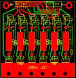
If you want to play with some 6s or 12s 431 balancers, I may have a few left over pcbs.
Not hard to find balance only boards.
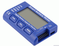
Or use a smart meter. <$10 balances lto fine.

6s 431 adj.gif


Meter 6s.gif
 
I agree there are some reasons you might want a lower balancing voltage. Most typical Chinese units are set around 4.2v.

Alan pointed out some reasons Zener diodes wouldn't be great for this. One other is the leakage current will be pretty high when the cell is anywhere near the zener point and will tend to drain the cells if sitting for a long time.

The board Inwo showed could be paralleled to an existing BMS to lower the balance voltage. The HVC and LVC of the BMS could stay the same and still function, but when the external board is connected, it would just drop the balance voltage.
 
Sunder said:
BMSes do a lot of functions, but really, if you design well, you only need one, and the others are "acceptable risks" (to me anyway).

1. Pack overcharge - Unless your charger has a catastrophic failure, this should never happen.
2. Pack over discharge - Unless your load has no LVC or an inappropraite LVC, this should never happen.
3. Pack overcurrent draw - May be useful in case you have a short, but a fuse can do the same thing.
4. Cell balance/cell overcharge - This is the key one I'm interested in.

Number 1 and number 2 are not the BMS's actual function. They are the function of the items you list--the charger's HVC, and the load's LVC.

The BMS versions of those functions are *cell-level* HVC and LVC, and are tied in directly with number 4, to help keep the cells balanced. If there's nothing to detect those and shut off pack input and output, it doesn't protect you from a cell problem (or a potential fire).

If a cell (group) has a problem, without those functions, you have no way of knowing it because it'll almost always be a problem where it goes too low during discharge, then too high during charge's higher current stage (and then drop below the balancer voltage when charge current cuts off).

While a BMS that doesn't cut off charge current at all based on cell-HVC might eventually balance the pack, you'll also have to have balancing resistors (or zeners or whatever is used) that can handle the higher bypass current the charger will be putting out at extreme unbalance--otherwise you end up with other cells charge up higher than they should (higher than they would with a regular BMS, probably), even though they get drained down eventually, it's unknown how high they'll actually go.

Say you have a 10s pack, and you end up with a cell group that drops to 2v because of a problem with it, before the load's LVC shuts the load down (because the BMS can't do it as it doesn't have anything to detect the cell problem). Then you recharge with a 41v charger (nominally 4.1v/cell). Say the other cells all charge up normally but the other cell is still down at 3v because it's really bad. 9x 4.1v = 36.9. + 3v = 39.9v.

That leaves 1.1v to spread across the other cells, probably evenly, so they all end up at 4.22222v, not a big deal, but the BMS's shunting resistors have to handle that excess voltage as excess current/heat, so they have to be sized to deal with this (because there's no shutoff to protect against overcurrent). If the shunting resistors can't handle it, they'll overheat and fail, and now there's nothing to balance the cell groups those fail on, so those cell groups can now become overcharged and won't get drained down from it. The problem will get worse and worse as that group absorbs more and more of the overcharge each time (as it'll already be closer to full than the other cells, moreseo each cycle).


Let's say the original problem gets worse and the other cell gets to the point it never goes above 2v anymore, now the excess voltage on the other cells is 2.1v, to spread across 9 cells is .23v overcharge on each cell--but if the other cells aren't all evenly matched anymore then the overcharge is even higher on some, and the risk of fire from either current thru that low cell or the overcharge on other cells keeps increasing.

A BMS with cell-level HVC wouldn't let this situation occur. It'd be turning the charger current off once any cell reached the balancing point. Teh charger would cycle on and off and never "finish" the charge and stop, and this should indicate a problem to the user that the pack isn't balancing and a manual check of voltages would show the actual issue.


Another fire risk is cell reversal, because that low cell could also cause a problem during discharge, where the load LVC is not tripped because the total pack voltage isn't low enough, but the cell itself has no actual content, no capacity, to deliver any current--it's now just a resistor in the pack, heating as current from other cells flow thru it.

A BMS with cell-level LVC wouldn't allow that situation to occur--the pack would not output any current with a cell that low in voltage, so it couldn't be used until the problem was determined and fixed.


The simplest BMS schematics I know of that we have easy access to, that will do all of what you need, is the Fechter/Goodrum BMS, last version of which was the Zephyr, IIRC. I'd recommend looking up that thread to see how it does what it does, and if you want a "cheap" BMS with custom voltages, use that schematic but use the version of voltage detector chips that give you the cell-level HVC/balancing point and LVC that you're after.


note that if your cells are good enough quality, or are sized so large vs your usage that you never run them down much or place much of a load on them, you probably dont' need a BMS at all--I don't run one on the EIG packs because that's how I'm normally using them, and they don't get out of balance enough to worry about (hundredths of a volt, if that).
 
Thanks everyone, for the detailed feedback. A lot of this has gone over my head, so I'm not sure where to take this from here.

My first thought is that I just build a set of aligator clips with a voltameter and a big 100w resistor, and build a big 2.7v charger, and do a manual balance as needed...

My second thought is to see if I can find some high quality Zenners and only attach it when I need a balance. I had read that good Zenners can be reliable within 1% - so much so that they're used to calibrate other voltage sources.

My last thought, prompted by Inwo, but not understanding his post, that perhaps I could modify an existing BMS - Surely a good BMS would use some sort of Voltage Trigger or Voltage comparator. Would it be possible to change the reference voltage to what I wanted?

I'm not sure where to head on this one, so further advice would be appreciated, or even resources to read to help me better understand the earlier posts.
 
Lots of guys have used Battery Medics:
https://hobbyking.com/en_us/hobbykingtm-battery-medic-system-2s-6s.html?gclid=EAIaIQobChMI65-r-7Se1gIVQ7jACh3LxACtEAAYAyAAEgL4bfD_BwE&gclsrc=aw.ds&___store=en_us

Programmable and pretty cheap. Not always reliable so measure with your voltmeter to verify.
 
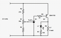
Pcb is 6 of these.
Shunt-nf.gif

431 is a shunt regulator like a zener, but is adjustable. Transistor helps handle more current.
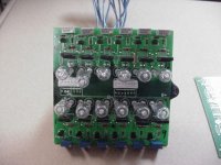
I generally use bi-pin lamps in place of resistors.

12slamps.jpg
 
I also am looking to see if there are any cheap BMS to balance a 72 cell LTO pack. I don't think there will be any cheap ones because these cells are so uncommon.

Maybe something like the one this guy is trying to create would be the cheapest balancer.
https://endless-sphere.com/forums/viewtopic.php?f=14&t=87372

The battery medic may be also worth a shot, but not sure with the LTO cell voltage range of 2.0 to 2.7 volts.
 
Not because of lto. Over 32s are rare in any case. I've used lto for a couple years.
If it was 64s you could use two, but over two is complex.
20s are under $100. If serious you might try 4 18s lto and isolator pcbs.

What is your budget? About $1500 will get you high power active balancers. Virtually unlimited cell count.

Steve is the lto guru. Must have several hundred cells for his projects.
He may have extra 20s lto bms if you want to test.
 
999zip999 said:
Why LTO low voltage and lots of connections.

Advantages make up for short comings.

Virtually indestructible if not grossly overcharged. Run dead and let sit for two years. They will rise from the dead and work fine.
No worries about c rate. Super safe.
 
Same reason I'm using - Making it elderly dad proof.
 
Inwo said:
Not because of lto. Over 32s are rare in any case. I've used lto for a couple years.
If it was 64s you could use two, but over two is complex.
20s are under $100. If serious you might try 4 18s lto and isolator pcbs.

What is your budget? About $1500 will get you high power active balancers. Virtually unlimited cell count.

Steve is the lto guru. Must have several hundred cells for his projects.
He may have extra 20s lto bms if you want to test.


Who is steve? There are LTO bms out there? Can you send me a link of one, I couldn't find any.

Thanks
 
Steve is a local buddy I met here.
Had to look him up. @emiyata
When I ran out of lto he bought back some of the lto bms I had.
I don't believe you will find a low cost 72s bms though.
24s bluetooth lto is $200 32s about $300. I'm using one 24s and have a couple extra.
Previous I posted a scheme for connecting bms in series via an isolated pcb connection.
The real answer, and Steve may agree, is the active balance solution.
If you are using new non-surplus cells, budget must be pretty high.
 
How deep are you in the project?
Any chance of reconfiguring to a 60v or 72v system?
Then use a common 24s or 32s bms.
 
One more practical idea.
Have Steve get you 3 pcs 24s lto bms. Thinking maybe $300- $400.
Then use 3pcs 24s chargers.
Or even 4pcs 16s bms.
I've used as many as 12 chargers on a battery. Not as goofy as it sounds.


Active balance picture:

c5c264df0449a3472dd7231edb0582981d9fcdd7.jpg
 
r said:
Yes 72 cell all in series, 1.5 volts-2.7 voltage range.

Orion BMS? I pulled one out of a working Prius retrofit with more than 78s. Lots of communications.
 
Lucky if you can get one second hand, but they are pretty expensive if you buy them new. Unfortunately, neither electric nor hybrid cars have taken off in Australia, so modified versions with custom BMSes just aren't available here.

I am being seconded to the UK end of next year though, so hope to bring back lots of second hand parts. Outlander PHEVs, the car I own is one of the best selling hybrids over there apparently.
 
INWO,
Building a pack/case for my bike with the 30 x 11ah. I ordered a 30s BMS, but it does not have balance function.
Have you found it necessary?
How would you wire the 2.7V Cap balance modules?
Could I setup 3 x 10s modules together?

Also, do you think just folding and crimping the Al tabs together be go enough?

Thanks!
2I3JuXtT1Ar-qN-7lzYX0QOgmQKMHa05DrqL94RYemGiPYvywiqL_KMdHEyNwQ2-ObtB3OtaZm2K3Yc9ABoJ0lR8hu2iZaflUfKXgYwwhd-kEYyP7oPVBqVxfvSY-hhELe0If_SVnbIjlOwq9lV7xJqzNekxV9Qloggu5hkyAmbUv4kOCfFR1fSXcK58InYSOwk_Pn5TEFo0mtcxmaNLr8cisIKqDHkemfw5qSfvCd8lc8ZcUISL6YgGXNeCbhX1hT305MxiaCoW1Nkd-7g5iz5dbarAdKPObAXYYjt9PGNaTsDZQyezeP8wj0gQ8ZDoC8EKvMYZw-YR1_cpbv7h8-5gtZUcLmaZXt6SdZ3-LPY1IvOQLQgCmBQllsC_h5B0geMzChZxdFb_tinzv9jBNgiw6Hme98L7auvejxthPrl-73F215PLmOyCfv1Kr-LOxAJqaGkmZI0QDTbruhQY4PL68dp0w0-O6kyaGTdKyokIiUUkdca7M2mrVNx3iZd5kGLF0TD4S2cNByJEgLWaEbS4pnkSxvd0v9afkQDOMIsJqzq5gOlndgcUTTrUzzCrCJtEM3lLitJbQrDDBrGFRh90ec_4wFlh6_oa_aO3Ku8=w484-h860-no

9Cz4qdFQdwC0RiUISOtBHWtRSDtf6v6y2LVXci1lAlxkowqEFj5zokuBl5-iseqVCrwTjgFXkZ51A5fSGo0VhHrFURg12Wb2E4Y4juTUKe9eJU4RWKn7acG3gqRi8z4xKjaCqDvKiIGTB8BCntCgEj-TAEt3ZEvgV64W9GUc7q6jTTOs9AzTrCcPetQ0sifWiCmyFQV2DP9WPrOPkyzkqp2uBzcN4IJn_U4xGNcebSOdRlnW6XsNkAkKACrUJtRzCixitIXeSwnv_mnUVy_ndmluxxf0hkb-g_albPbsCb30-N4KrNvb1hLNKgj-f02eFAqufSaSdzL-rQ-EnXZJL8Lx3mr5zSklgdZ_st-ArtgToHrRXFrQDx9jgzpBUGWmJMG6hAr35uV9Pjs0ysKQty_klXxEi3dVynQKOUYyHc-JF11Wz1yiCUEr8GScvDWA5c7lXtmcpU8cxbdPMPVeAm-fzCrYLmBe1K-2MmOKkMQKYVFQx6l-Ekhm7GY1Ayx7TV9D6EMeIuHqm76IyG0OLOCFRsmLKhCEZHWdWZ0zXE_y72jBVfjKi246GQQrfacBYTdJB4Jh6xzSyoN8zIMiy04LCpiS_JeJrmM95bND_AY=w484-h860-no

Hr9wgyiMDxbPvMPZ5_X_HlPA0_Xomf6qPl-nb8vWC9xv-_Mz4euzXueq9HWLAJpmW9hO3gc3aJ2bWdDCYkJkG4WUfCNZa2NIa1KuzFENH5TTIuXdHtlPcMMGFcGTQKGVUShH6rxYlYwoCpISGdQFdTZS08Jtyloh9q3Q2YDNdqVA23eqwxGfS-wxzN5F3bxXpr7cGmLHZgSfRn8-Bp-hQ2ygUhCIRmhZQ1K2W9Ls1DORgEY20YtJ036-Z_F64Ob75u6BVBEFSd6Pwt5jCbpSk20HVu0f39N3wGbvCd8ylE9rkTRhzQjsX1mWtbTwepdyT9lppdFifjyZs69RFEtIVz_mNMQBXYeasQqo2EmOM1vpgfAoTc_M0lrcsZcnSBGRaLuOK0OrVG2shJJjMe7ETjzMs_ylBcX0nTpWhuo_O2xFwKXQqjXH50rIKPjKkg_4AYu1Bdr4E47PUfIpuE1e9DKNWcvbiXfGxgQyeEas9aFXQMnZKzd1akOw88PW9aA9sWwV0CjZrcVWFE4YwYK1zf0l4wTRIewBsV2FLEKqbmv-su3VtR3-QcAn4yiQnirLXb4SvU2nN9zgJUA5_3S9oLJkcyxn5WvxiS0_CAHNR-s=w1529-h860-no

BcoyTbXq9kwgfpvV4zAbcCfFIUS2cWRD9trv3L4RlDJekqqltziIg2FLQvE1ZJ5LxvhWjQyNLC_7ZeiKzPc3rJprrCiKd4pKgDOgM-Bti5entpXIuYVznCulI8ELB6Wc2BVnWtsT6PM8bVhy4a4N1mDnDH6mmzroMpnmBUKSoym59Pbv6BbI8pM-X-oJ_Sa8-r_RYVJOCRT-ivyUgVZeGdRWuaHQ8BFPlXdIZXZDbA7-Sl3S_BvuMhxEgoiPbV41JP42QGUHD0JAYlj7RHT_HpLgpqNtAJRkShcJajuSj7at9NfiYLvG1dnQVGJskQCTKVREALa9cvdsUYgzOi9QtCsS-6B4JpTfnp3YUa0TqN4ZSIXzkVvay2GbkHuZcE6ZtbD_NZ0lhOBQUyboL05X06xH3glooXUokJ1V3L-HV0RAFUeP1nXJPQRWz8cqffwtkWX41cOXsc3Hz5gYZWFBWy1royJgqnPemiwLGIiJ6QuCpYit3Xndbrh1rV82eTjfupGqw0xx_J43Z6hFhpEauIhKtv0OCIRNeqhzD2UAwBSlrq1H6FSYOapxWHcyrqeejVJ8RNp1p-f28vjY-VuA-4Ocfo5roQVngNeT793Byis=w484-h860-no
 
Are you using the battery case as a stressed member? Because otherwise, those right angle frame joints are going to be none too happy.
 
Chalo said:
Are you using the battery case as a stressed member? Because otherwise, those right angle frame joints are going to be none too happy.
I am but even then this is plenty strong - Did some calculation and this is stronger then the original frame.
 
Just because the tubing is stronger does not make an unbraced truss as strong as a braced one.

I'm guessing the top tube to seat tube joint will go first, because it's the corner of the unbraced square with thin walled tubing on both sides.
 
Back
Top