LT6820 Not Working Help Needed

NeighborVadim

100 µW
Joined
Sep 9, 2017
Messages
7
Hello,

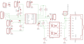
I've been working on a custom BMS utilizing the Linear 68xx chips. I have a BMS board working, but I am still trying to get the isoSPI communications bus working. I have designed a small board utilizing the LT6820 chip and the HX188nl pulse transformer, but to no avail. I am using this board with a confirmed working DC1894 demo board from linear, but I am getting no data back from the demo board. I have attached the schematic. Any help is welcome.

Thanks
 

Attachments

  • schematic.png
    schematic.png
    10.6 KB · Views: 1,046
Maybe try it with the transformer bypassed. Alternately, put a scope on the RX and TX lines and see how they look right at the input. The transformer might be distorting the signal enough to not work.
 
Thanks for the quick reply! I just hooked it up to a scope, and the IsoSPI appears to be coming through loud and clear. Maybe the DC1894 board is broken? Still open to any ideas.
 
According to the demo board schematics, and looking at the demo board traces it appears not. I can try bypassing the RJ45 anyhow. My other idea is that there is an issue in the code I'm using. I'm using the default DC1894 demo board code (which worked for my board with the LTC6811) ,which may require modifications to operate with the LT6820.
 

Attachments

  • DC1894.ino.txt
    15 KB · Views: 109
A few quick comments... The transformer you're using has a common-mode rejection transformer (horizontal schematic core & windings) and an isolation transformer (vertical). In the application information on page 21 they show the LTC6820 connected to the common-mode transformer then the isolation transformer - it's backwards on yours - and the isolation transformer center-taps only the cable side has the center tap connected through a capacitor to ground and the other side is a no-connect.

If you are just testing on a bench with the grounds on each end the "same" (there's no such thing really!) then the transformer concerns wouldn't prevent things from working.

What cable are you using and how long is it? I might be able to take a look at the code tomorrow depending on my customer load. Probably need to know more about what's connected to the SPI ports to really help....
 
Thanks for the pointers! I have been running it with two separate power supplies, but it couldn't hurt to try connecting the grounds. I would think that the transformer issues are not a problem as I can see the isoSPI pretty clearly when I hook it up to a scope (https://imgur.com/a/UrDMx). As for the cable, I'm using a 15cm rj45 cable. I'm not sure what you mean by "what's connected to the SPI ports" but here is a general diagram of the setup:

Computer --> (serial) --> Linduino --> (SPI) --> LTC6820 Board --> (isoSPI) --> DC1894 (LTC6804-1 demo board)
 
I agree that the transformers are very unlikely to give you any grief with a common ground. If you spin it around and get the common-mode and isolation corrected and remove the cap on the cable side center tap you shouldn't have anything to worry about common ground or not. If there is AC potential between the grounds that could mess you up though the way it is (DC wouldn't do it since the center taps are connected to ground through a capacitor) and could cause the transformer cores to saturate and really screw up the signals.

Linduino on one side and DC1894 on the other - got it. Main thing is to get clock polarity proper (is data on rising or falling edge of clock?).

These LT isolators are very nice albeit expensive. I haven't used this particular part but 'm familiar with some of their others...
 
The Linear chips aren't that expensive in my opinion. $5 for a isolator chip and $10 for a 12s BMS chip seems pretty reasonable IMO. When I get back to the bench tomorrow I'll be able to test it with a common ground. As for the clock polarity, from what I gather from the Arduino code and what I've seen on the scope it seems that the Arduino is operating in SPI mode 0, so I've set the LTC6820 to have PHA=0 and POL=0. Thanks again for all the help, I'll get back to you with the results from the connected ground test!
 
Isolators aren't inexpensive no matter and for our "G-job" projects $5 is pretty who-cares. I've got some customers that don't worry about that sort of cost but I've got others that don't take $5 interface devices all that well ;-}

Good enough. I'm too slammed to look at the code for a couple of days regardless.
 
Hey, sorry for not getting back quicker, normal work got in the way. I did a connected ground test, but still nothing. There is literally just no signal on the miso channel. I took a look at the isoSPI coming through, and it looks good, maybe something is wrong with the ltc6804 board. Did you get a chance to look at the code?

Attached is a picture of the isoSPI channel and the MOSI channel.
 

Attachments

  • IMG_20171026_1220298.jpg
    IMG_20171026_1220298.jpg
    374.2 KB · Views: 1,377
I got hit with a $$$ job reviewing a monster design (2 FPGA's, an RF ASIC, coretex-A9, etc.!) and heads down in that and I'm also doing a personal ebike project with (just a coretex-M4 with wifi, but still a ton of work! - at about 2K LOC at this point) so very little time all of a sudden... :-/

Can you give details of exactly which pins those scope traces are?
 
Back
Top