Generic-Chinese-Bluetooth-BMS-communication-protocol

simat

10 mW
Joined
Apr 7, 2013
Messages
29
Location
Harvey, Western Australia
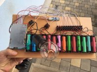
There are a number of generic Bluetooth BMS units based around the TI BQ76940 BMS controller with a number of different configurations. I am not sure if they are manufactured by one or a number of different manufacturers. The thing they have in common is that they can be used with an Android app called xiaoxiang and with a Windows program called JBDTools.

This is the command sequence sent by the JBDTools software to obtain the battery information. It is a binary string which in HEX format is. I have added the EOLs for clarity.
DD A5 03 00 FF FD 77
DD A5 04 00 FF FC 77
DD A5 05 00 FF FB 77

First two bytes are the header, bytes 3 and 4 are the command, bytes 5 and 6 are the checksum, the last byte is the EOR.

The battery current along with other information that I haven't decoded is returned by the BMS board by the first command. The second command returns the individual cell voltages and the third returns the BMS name in ASCII format and maybe other information.

The reply packet is a binary string in HEX format is. I have added the EOLs for clarity
DD A5 00 1B 13 78 00 00 00 00 03 E8 00 00 22 C7 00 00 00 00 00 00 19 00 03 0C 02 0B 64 0B 5F FC 83 77
DD A5 00 18 10 39 10 3A 10 38 10 3A 10 3C 10 39 10 37 10 39 10 3B 10 3F 10 36 10 3A FC 74 77
DD A5 00 14 4C 48 2D 53 50 31 35 53 30 30 31 2D 50 31 33 53 2D 33 30 41 FB 39 77

The first two bytes are the header, bytes 3 and 4 are the length of the reply data in bytes, the data follows followed by the checksum, and finally the EOR.

The battery current is in bytes 7 and 8 of the first line

The second line are the individual cell voltages. Each voltage is a 16 bit number so 0x1039 gives a voltage of 4153mV
10 39 10 3A 10 38 10 3A 10 3C 10 39 10 37 10 39 10 3B 10 3F 10 36 10 3A
These converted to decimal in mV are 4153 4155 4152 4155 4157 4153 4151 4153 4156 4159 4150 4155

Third line is the BMS name.

I have written an interface between BMS boards that use this protocol and my BMS software if anyone is interested. A link to my BMS software is in my signature

Simon
 
I have done some further reverse engineering of the coms protocol for these BMS.

I have decoded the majority of the Config settings that are displayed in the config tab.

To read the config settings you first have to read the battery data information with these commands
DD A5 03 00 FF FD 77
DD A5 04 00 FF FC 77
I don't understand why you have to do this but you can't access the config data unless you do this first.
Then you have to send the following preamble command
DD 5A 00 02 56 78 FF 30 77
then you send the commands to access the registers you want to read, for example
DD A5 10 00 FF F0 77
will return the Full Battery Capacity register in the form
DD 10 00 02 07 D0 FF 27 77
The DD is the message header, 10 is the register number, 02 is the number of data bytes. 07 D0 is the data in binary which equates to 2000 decimal, FF 27 are the checksum and 77 is the EndOfRecord marker.

You send as many read register commands as you want which range from 10-3F and A0-A2 and AA.

You finish off the read with the command
DD 5A 01 02 00 00 FF FD 77

Writing to the registers is similar
DD 5A 10 02 4E 20 FF 80 77
where the 5A means write, the 02 is the number of bytes of data and the 4E 20 is the data to be written.
I have made up a spreadsheet with all the registers I have decoded to date, or if you want a PDF.

Does anyone know what the "protected count" section of the config tab is about. Is it the number of times a particular fault has occurred or something else.

Simon
 
I like this a lot. I just installed a 10s one on a friends bike. would be nice to have an Arduino with an oled display for the voltages rather than a phone on the handle bars.

thanks for posting.
 
Here is web app to monitor/control multiple BMS devices in one battery pack:
https://mono.software/2018/11/15/multiple-bms-monitor/
 
Here is the instruction book I received when I requested it from a vendor. It is instructions for a windows version of the JBDTools software for windows. If anyone finds more english or chinese instructions for these devices I would like to find out about it.

https://drive.google.com/open?id=0BwXiTsImatXzTEFvU3IwYUN0MjdWU2kwemRjQ0Y0Z2Q1WGtF

ifishtoo
 
It appears to have a primary and secondary over current protection.

Q. What happens when the set threshold is exceeded? I will post when I find an answer.
The online instructions have a few tidbits in english. https://www.lithiumbatterypcb.com/smart-bms-software-download/
 
mario1122 said:
Here is web app to monitor/control multiple BMS devices in one battery pack:
https://mono.software/2018/11/15/multiple-bms-monitor/

Thank you! That article has a misleading name. There is a reasonable amount of valuable info about these bms.
 
Hi,

@simat : Thanks for the work.

I built a little test setup for the "China BMS".

The data is read with a Pi-Zero running gatttool.
With the 3 read commands, I found a lot of things and did a little tinkering:

Packvoltage: 52.80 V
Amperage: -.23 A
BMS Name: LH-SP15S001-P14S-60A
Cell#: 01 02 03 04 05 06 07 08 09 10 11 12 13 14
Volt :3.73 3.83 3.71 3.79 3.75 3.69 3.81 3.84 3.72 3.83 3.76 3.72 3.77 3.79

But also with the registers from Excel I am missing some values that the Android App is showing:

SOC%
Temperature
Temp Sensor1
Temps Sensor2

Also it would be nice to controll the charge/discharge switch.

Does someone know additional read/write registers?
 

Attachments

  • IMG_3470.JPG
    IMG_3470.JPG
    65.9 KB · Views: 13,938
This link gives information on the 03,04,05 commands that give the information you want

I have had limited success with switching the charge and discharge FETs on and off with the following.

send
DD A5 03 00 FF FD 77
DD A5 04 00 FF FC 77
DD 5A 00 02 56 78 FF 30 77
which is the same as getting the config data then
DD 5A E1 02 00 03 FF 1A 77 turn both FETs off
DD 5A E1 02 00 02 FF 1B 77 charge FET off, discharge FET on
DD 5A E1 02 00 01 FF 1C 77 charge FET on, discharge FET off
DD 5A E1 02 00 00 FF 1D 77 both FETs on
then
DD 5A 01 02 00 00 FF FD 77
I have been having a few problems with this but haven't had time to fully investigate.

Simon
 
Thank you.

I will do the MOSFET thing and tell here how it works.
SOC is only 1byte, therefore I couldn't identify it, because I only checked for 16bit values.
 
I just wrote up a long thread asking people if there are any of these UART BMS units with a known protocol. I almost hit send and then decided to check again on ES....found your thread! nice work!

Do you have any recommended BMS unit sellers? I also haven't had an easy time getting sellers to tell me what chip they use to confirm if it's based on the TI chip.

My end goal is to communicate via optoisolators to 3 bms units that are in series (for now ignore the mosfet output voltage issues in this , I can explain later) and monitor basic voltages. I plan to use a teensy or similar MCU as the central monitor of the multiple sub bms units.

I look forward to digging into what you've done so far! Thanks for sharing.
 
Kin said:
Do you have any recommended BMS unit sellers? I also haven't had an easy time getting sellers to tell me what chip they use to confirm if it's based on the TI chip.
This is where I got my latest batch of BMSs, https://www.aliexpress.com/item/15S-Smart-Li-ion-Battery-PCB-board-Bluetooth-Mobile-BMS-for-63V-Li-Ion-Ebike/32812066109.html

I am fairly sure that any of the units using the xiaoxiang android ap or the Windows JBDTools program will be using the TI chips. The TI chips are controlled and the comms is done by an Atmel microprocessor on these BMS boards.

My end goal is to communicate via optoisolators to 3 bms units that are in series (for now ignore the mosfet output voltage issues in this , I can explain later) and monitor basic voltages. I plan to use a teensy or similar MCU as the central monitor of the multiple sub bms units.
If you wanted to use the FET cut out switches on the BMS you could just use the ones on the BMS board connected to the battery minus and upgrade the FETs to ones that could cope with the higher voltage.

Simon
 
With 45-48S as my likely total cell voltage I end up feeling like it's easier to have the bms units drive relays to control power to a main contactor. I still need to work through whether the quiescent current draw will be too high as a result or if I turn on off the relay when the car us off if the on in-rush current would be a problem for the contactor.

I dont love the idea of three bms units with such high voltage fets >150V) nor am I 100% comfortable with say 4110s for each chain and a diode to protect the 4110s in case one bms shuts off. Realistically the first version will just not have output control protection and that should be ok if my mcu is monitoring the bms units through the uart

It is unfortunate for me that this particular chip is only good to 15S cells, since my batteries are available in 8S modules I would be much better off with a bms with uart that could do 16s.
 
Kin said:
With 45-48S as my likely total cell voltage I end up feeling like it's easier to have the bms units drive relays to control power to a main contactor. I still need to work through whether the quiescent current draw will be too high as a result or if I turn on off the relay when the car us off if the on in-rush current would be a problem for the contactor.

I dont love the idea of three bms units with such high voltage fets >150V) nor am I 100% comfortable with say 4110s for each chain and a diode to protect the 4110s in case one bms shuts off. Realistically the first version will just not have output control protection and that should be ok if my mcu is monitoring the bms units through the uart

It is unfortunate for me that this particular chip is only good to 15S cells, since my batteries are available in 8S modules I would be much better off with a bms with uart that could do 16s.

All cell count up to 30s are available for these boards https://es.aliexpress.com/store/group/20S-to-30S-smart-BMS/1379203_514039624.html?spm=a2g1y.12024536.pcShopHead_8538170.1_0_4

If your specific cell count is not there, just ask the vendor to do one for you (they configure the cables and firmware before sending to you)
 
That's great work. Thanks for posting.

If they use TI chips, would the datasheet for the chip tell us about the available commands?
 
trazor said:
All cell count up to 30s are available for these boards https://es.aliexpress.com/store/group/20S-to-30S-smart-BMS/1379203_514039624.html?spm=a2g1y.12024536.pcShopHead_8538170.1_0_4

If your specific cell count is not there, just ask the vendor to do one for you (they configure the cables and firmware before sending to you)

Thanks Trazor! I had skimmed the datasheet for TI BQ76940 , and found it was only meant for 1-15 cells. Do you know the 20S to 30S options are using the same chip? They maybe are using multiple chips, which would be OK, I just wasn't sure when looking at higher voltage 'smart bms' options if they are actually the same as what simant found.
 
Kin said:
Thanks Trazor! I had skimmed the datasheet for TI BQ76940 , and found it was only meant for 1-15 cells. Do you know the 20S to 30S options are using the same chip? They maybe are using multiple chips, which would be OK, I just wasn't sure when looking at higher voltage 'smart bms' options if they are actually the same as what simant found.

There are three variants of the BQ76940, the 76920 has five cell inputs, the 76930 has 10 inputs and the 76940 has 15 inputs.
Any of the BMSs that handle more than 15 cells do indeed have more than one TI chip. The 'high voltage' chip has its I2C bus coms opto isolated so the Atmel processor can talk to both of them. I am not sure how they handle the charge and discharge FET enables from both TI chips.

Simon
 
fechter said:
If they use TI chips, would the datasheet for the chip tell us about the available commands?
I don't know of any way you can get the Atmel processor that runs the BMS boards to send 'raw' commands to the TI chip.

You could remove or disable the Atmel chip and talk directly to the TI chips via I2C bus if you wanted to.

Simon
 
simat said:
I don't know of any way you can get the Atmel processor that runs the BMS boards to send 'raw' commands to the TI chip.

You could remove or disable the Atmel chip and talk directly to the TI chips via I2C bus if you wanted to.

Simon
I see, there is an intermediary Atmel that talking to the outside. It would be great to get the source code for that (but not likely).
 
fechter said:
simat said:
I don't know of any way you can get the Atmel processor that runs the BMS boards to send 'raw' commands to the TI chip.

You could remove or disable the Atmel chip and talk directly to the TI chips via I2C bus if you wanted to.

Simon
I see, there is an intermediary Atmel that talking to the outside. It would be great to get the source code for that (but not likely).

I made open source firmware for it: https://github.com/BotoX/xiaomi-m365-compatible-bms
 
Since this topic isn't that old, I received this spreadsheet (was in Chinese) for the data transmission protocol. I roughly translated it with Google/Microsoft, and added some notes. Hope this helps!

https://www.dropbox.com/s/03vfqklw97hziqr/通用协议 V2 (支持30串)(Engrish).xlsx?dl=0

I'm working on an arduino library that gathers the data from it nicely. Work in progress.

EDIT:

While trying to enter factory mode, instead of sending the 0x03 and 0x04 commands, I noticed *for my board* that just sending enter factory mode twice will successfully let you enter "factory mode". Can someone confirm this? (@Simat 😊)
 
AadamZ5 said:
Since this topic isn't that old, I received this spreadsheet (was in Chinese) for the data transmission protocol. I roughly translated it with Google/Microsoft, and added some notes. Hope this helps!
That looks super helpful. Thanks for posting it.
 
There may be some useful information here in relation to this BMS device.
https://github.com/bres55/Smart-BMS-arduino-Reader

The handshaking was the tricky part. Not sure I fully understoood it, but it worked.

screen%20shot.png
 
Back
Top