A123 20AH LiFePO4 cells interconnexions

Joined
Jan 29, 2016
Messages
941
Location
Shanghai
Hello guys,

I have a nice opportunity to purchase some A123 20Ah pouch cells, and I'm now wondering what method I should use to connect them together in series.

My main problem is that I don't have a lot of space and I plan to build a rather huge battery (24S 4P, so about 72V 80Ah).

So basically I would like to avoid using bolts and aluminum bars to connect each tab with the next one, because it would be too tight of a fit in my battery box and I cannot really make it bigger than that.
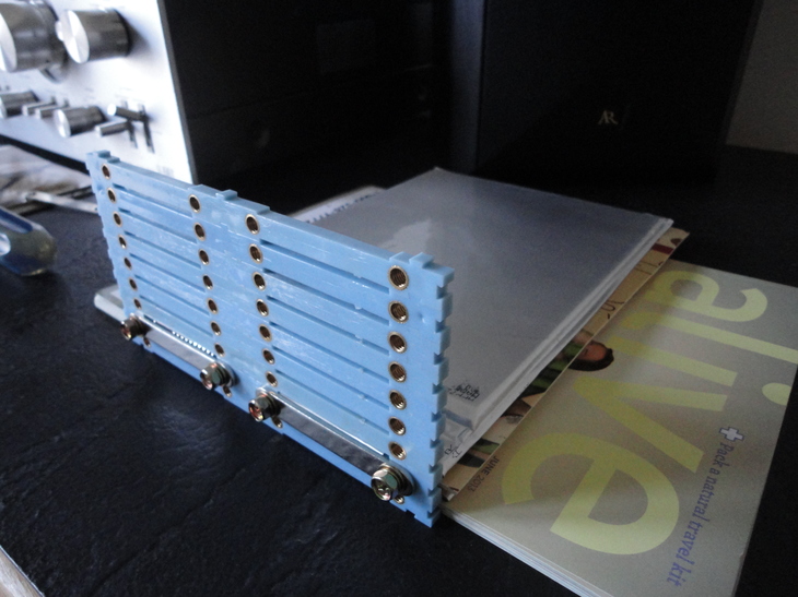
My idea so far would be to build some little PCB connectors, reinforced with lots of solder, and solder the pouch directly on these.

I believe the main concern here would be the heat during soldering, so my plan would be:
-Cover the entire PCB tracks with lots of solder
-Cover the tabs with a thin amount of solder, then cool it quicky using compressed air
-Press the tabs on the PCB
-Heat the whole thing so that PCB and tabs will be permanently attached, then cool everything quickly using compressed air

Goal here is to reduce the amount of heat going to the tabs, so that it doesn't spread to the cell itself. I think the amount of heat should be low enough to have no impact on the cells, but I'm wondering why it seems like so few people seem to use this kind of technique?

Is there any drawback I haven't think of ?
Any advice would be welcomed!
 
Just to make it a little clearer, I drew a mockup of what a portion of the battery would look like:

89e7e04466d697c9077a760a1c7e3016-full.png


The red brackets will be 3D printed. The cells will be connected in series through some small PCB including one lead per cell to the BMS
 
Be careful as there are counterfeit and ones that were taking out of old Karman Fiskars and someone try to spot weld a new tab on the short tab. Not a good idea . And then there's the famous machine that spit out many cells with crooked tabs. I bought mine 5 years ago and have good luck running as 24 s1p add up to 90 amps with 1170 Cycles so far no BMS I bought a through the sense wire balance charger but just don't need it.
 
Hillhater said:
Have you tried soldering to the Aluminium tab on those cells ?

Well I haven't received my cells yet, so no.
That's why I'm asking this question, I would like to get advices before actually doing stuff.

I've saw a guy on youtube soldering those cells, but he was using a sketchy method with a blowtorch, which I found a bit dangerous/stupid.
I'd rather like to use a powerful soldering iron and pre solder the tabs and the PCB to limit the heat exposure.
 
999zip999 said:
Be careful as there are counterfeit and ones that were taking out of old Karman Fiskars and someone try to spot weld a new tab on the short tab. Not a good idea . And then there's the famous machine that spit out many cells with crooked tabs. I bought mine 5 years ago and have good luck running as 24 s1p add up to 90 amps with 1170 Cycles so far no BMS I bought a through the sense wire balance charger but just don't need it.

Yeah, well since I live in China and those cells are not very easy to import (euphemism) I don't have many options. So I'll just go for those and hope they are not too crappy. But thanks for the advice anyway.

Any recommendation about soldering?
 
Mypack is all together in between alternating plastic and aluminum bus bars. Trying to solder aluminum tabs to Copper tabs I don't believe you will have success. They do laser well the two different Metals together
 
999zip999 said:
Trying to solder aluminum tabs to Copper tabs I don't believe you will have success.

That's what I believed too, but it seems that if you remove the aluminum oxide layer of the tabs they should be relatively easy to weld, without using any special flux or solder... I think I'll just try it and give you guys a feedback. I was just wondering if there were any concerns in terms of safety or something I haven't thought of prior to actually test this method. Like for instance the tabs heating too much during use, melting the solder back and ruining the pack. I suppose the tabs should stay way under those kind of temps anyway but it's always good to get experienced user's inputs prior to doing anything.

This thread seems to say that soldering on aluminum is actually doable:
https://endless-sphere.com/forums/viewtopic.php?t=32762

Thanks a lot for your inputs guys, I really appreciate. Any suggestion or advice regarding those cells and the ways to join them into a pack is very, very welcomed, so keep'em comin'!
 
If youre already machining or molding or printing cell holders for them, you could make them like the EIG pouch holders, which have embedded nuts just under the tabs. THen theres holes in the tabs (or rather, to the ?brass? tabs welded to the cell tabs), and they get overlapped over the holders nuts. THen plates or busbars or wire/lugs are bolted thru the tabs to the embedded nuts, which secures the tabs together and passes the current on to the next cell in series. +++


The cells can be simply in series, or they can be paralleled in groups of 2, 3, 4, etc. while also putting htem in series. Two of the EIG packs I use are 2p, and one is 1p.

Busbars would be the stiffest most clamping connection method, as long as the housing / cell holders teh nuts are embedded in are stiff enough.
 
amberwolf said:
If youre already machining or molding or printing cell holders for them, you could make them like the EIG pouch holders, which have embedded nuts just under the tabs. THen theres holes in the tabs (or rather, to the ?brass? tabs welded to the cell tabs), and they get overlapped over the holders nuts. THen plates or busbars or wire/lugs are bolted thru the tabs to the embedded nuts, which secures the tabs together and passes the current on to the next cell in series. +++


The cells can be simply in series, or they can be paralleled in groups of 2, 3, 4, etc. while also putting htem in series. Two of the EIG packs I use are 2p, and one is 1p.

Busbars would be the stiffest most clamping connection method, as long as the housing / cell holders teh nuts are embedded in are stiff enough.

Thanks for your advice amberwolf :)

I thought about that too, using brass inserts embedded in the plastic brackets. there are just a few things that I'm not a big fan of:
-It would imply that I'd have to somehow machine busbars out of aluminum or copper. Not a big problem but I'd need something like 95 of them so it would be quite a bit of work
-I'm not a big fan of screwed terminals in a vehicle that will experience a lot of vibrations, thermal variation and stuff like that, Sure I could use some thread locker but I would always be a bit worried that the connectors would loosen up at some point
-3D printed plastic parts are rather solid, but the clamping force needed is rather huge, so I'd worry a bit that the inserts would slip in the plastic bracket while tightening...
-It will add quite a bit of weight and would probably less compact, my battery box is only 26cm wide, which is one of the main problems I have.
-I believe it would add a bit more resistance than soldering (but I'm not entirely sure about that particular point)

The positive side would be that it would make the assembly and maintenance of it super easy,
I'll give this solution a bit more thought, since it really is much easier to build.
 
I built two packs made of 12S A123 20 Ah pouches.
Used screws and aluminium tabs to connect tabs together.
I would rather not apply so much heat to the tab which of course spread to the cell.
The best and only way recommended by A123 is weld .
 
Check out some of the posts from Inwo. He has done a lot of large, tabbed cells.

Here's an example:
https://endless-sphere.com/forums/viewtopic.php?f=31&t=91735&p=1372089#p1372089

My experience is limited, but you really need to find out what the tab material is. If nickel or nickel plated copper, you can simply solder them. If they are aluminum, soldering is pretty much out and you need something that clamps them. I have seen packs made with aluminum pop rivets. These need washers or backing plates on thin material. Having an easy way to make a hole in the tab is handy too.
Inwo made a punch tool from a pair of pliers.
 
Dui said:
-It would imply that I'd have to somehow machine busbars out of aluminum or copper. Not a big problem but I'd need something like 95 of them so it would be quite a bit of work
Once you work out the design, you could have them waterjet-cut by places like Bigbluesaw here on the forum, or any number of others.

As for the number of bars, is it really a 95s battery? (or 93s, with another bar at each end). Thats a lot of voltage.

If its instead the battery you describe in the OP, a 24s 4p, you only need 24 (26) busbars, because each bar would be 4 cells wide, kinda diagonal to go between the + of the lowest cell to the - of the highest.


-I'm not a big fan of screwed terminals in a vehicle that will experience a lot of vibrations, thermal variation and stuff like that, Sure I could use some thread locker but I would always be a bit worried that the connectors would loosen up at some point
-3D printed plastic parts are rather solid, but the clamping force needed is rather huge, so I'd worry a bit that the inserts would slip in the plastic bracket while tightening...

If the inserts have knurls or are otherwise not round, they wont slip, if theyre molded in. If you can find pics of the EIG hardware (theres some here on ES, and elsewhere) you can see how they did it.

Though the screws have standard split-lock-washers I didnt put threadlocker on the screws in my 14s1p EIG pack, and it stayed tight for the years I used it on our bumpy potholey roads, on my hardtail bike and trikes. It still sees occasional use but I tend to use one of my 14s2p packs instead, which also dont use threadlocker (I think I left the splitwashers off on the pack thats built into SB Cruiser, dont remember for sure). Ive only had them for a year or two, but again, no loosening so far.

I dont have to crank them down further than a 2mm allen key will tighten the ~3mm-wide fine-pitch screws without stripping the key or head or flexing the key.

-It will add quite a bit of weight and would probably less compact, my battery box is only 26cm wide, which is one of the main problems I have.

It will add some weight--how much depends on the thickness and metal you choose for busbars, which will depend on the current you need them to handle. But I dont think its that much weight. Maybe a pound or so if you use really thick copper. I recommend using the same metal as the tabs or tab extensions, to eliminate the possibility of electrolytic corrosion.

It shouldnt add significant height to the pack, perhaps a few mm depending on the thickness you already have for the mounting plastics and the thickness you choose for the busbars, and wont add any width unless you change the plastics width. The thickness simply has to support the pair of nut-serts per tab, or actual nuts if you go that route.

If you add welded copper, brass (or other) extensions to the tabs (to prevent electrolytic corrosion between differing tab metals, if the plus and minus tabs are different) then that may add some height, depending on how closely theyre attached to the cell on the tab.

-I believe it would add a bit more resistance than soldering (but I'm not entirely sure about that particular point)
Since solder itself has resistance that is probably a lot higher than direct contact between tabs, the only potential issue I can think of is if moisture can get between the tabs in the clamp, and cause electrolytic corrosion between dissimilar metals. As long as you use tab extensions of a single metal, that wont be an issue, or if the tabs are already the same metal.

If the tabs come wrinkled instead of completely flat like new ones, you may want to use a press to flatten them first to be sure they mate completely across their surfaces.
 
That's a good idea how he brought the tabs through a piece of plastic then folded them and then pull up plate on underneath and on top and screw them together that saves half the height. Can we see the size of your battery box. As they are the size they are. Plus what kind of vehicle is this heavy powerful battery for ?
 
amberwolf said:
As for the number of bars, is it really a 95s battery? (or 93s, with another bar at each end). Thats a lot of voltage.

No, plan was to do 4 packs of 24S 1P, then link them together in parraller through some anderson connectors and huge wires.
This motorbike is my daily driver so I need reliability. By having 4 batteries I can still run totally normally if one of them dies and I can still run at a slightly reduced power if 2 of them have issues. Meanwhile I can repair the defective units and still be able to go to my workplace.
It also leaves me the possibility to do different battery configs if I ever feel the need to go to 144V for example.

amberwolf said:
If its instead the battery you describe in the OP, a 24s 4p, you only need 24 (26) busbars, because each bar would be 4 cells wide, kinda diagonal to go between the + of the lowest cell to the - of the highest.

Well I cannot do that since I planned to do 4 packs.


amberwolf said:
If the inserts have knurls or are otherwise not round, they wont slip, if theyre molded in. If you can find pics of the EIG hardware (theres some here on ES, and elsewhere) you can see how they did it.

I have quite a bit of experience using 3D prints and brass inserts. They do slip if you apply too much torque. But that is not a very big issue here, I could use epoxy or whatever :)


Thanks for the other valuable inputs and suggestions :)


Well, there might be a different turn of events since yesterday. Turns out I might be able to find fully assembled packs using those cells, with warranty, compression brackets and 300A BMS for even cheaper that the cost of the cells alone (something around 450-500 USD for a 76V/40Ah battery).

I'm not entirely sure yet that I will go this route but I'm definitely tempted...
 
The thing I'm tired about with the A123 20 ah pouch cells is the weight of my 24 s1p pack. The weight of four of these maybe over a hundred sixty pounds. Now that's a heavy battery. Why do you need such a big battery?
I like to see what you are going to put it in ?
 
The cells themselves are 490g, so 96 of them works out to around 47kg, which is about 105lbs. That's just the cells mind you. As far as energy density goes, they're not very competitive with other chemistries.

But in terms of power density, at 200A continuous and 400+ peak they're still pretty damn good.
 
999zip999 said:
The thing I'm tired about with the A123 20 ah pouch cells is the weight of my 24 s1p pack. The weight of four of these maybe over a hundred sixty pounds. Now that's a heavy battery. Why do you need such a big battery?
I like to see what you are going to put it in ?

Most of you guys are using ebikes so I guess weight is important.
In my case it is an electric motorbike, and currently runs with super heavy lead acid batteries. So even if LiFePO4 is not the lightest cell technology, it is still way better than lead acid.

The specs I need for this battery are:
-Safety: I charge it every night in my garage, and I live upstairs, don't want to end up in a hell barbecue
-Huge current draw (currently 200Amps continuous, but I plan to at the very least double this power soon)
-Fair capacity for autonomy, hopefully 70-80km at full blast
-Needs to fit easily in the available space (wasn't easily doable with 18650 cells in my particular case)

Those cells fit all my requirements, the only drawback is indeed that they are a bit heavier than other chemistries.

Here is my motorbike:
file.php
 
#1 safety. Yes I found the high quality of these cells is the #1 they stay balance just bulk charging. What is the source for these cells and how much will you be paying ? I understand the need for a strong battery with that bike. What motor and controller do you run. Nice ride. Taking the lead out and putting some high-powered cells in you would have a hard time keeping the front wheel down
 
999zip999 said:
#1 safety. Yes I found the high quality of these cells is the #1 they stay balance just bulk charging. What is the source for these cells and how much will you be paying ? I understand the need for a strong battery with that bike. What motor and controller do you run. Nice ride. Taking the let out and putting some high-powered cells in you would have a hard time keeping the front wheel down

Thanks :)

I'm using a 3000W QS motor and a software unlocked version of the sabvoton 72150, currently set up at 200 Amps continuous.
That's nice but not really amazing in terms of perfs so far. About an equivalent to a 125 or 200cc bike I guess.

I plan to make some mods to the sabvoton, using shunts to the current sensors to hopefully go around 300-400 Amps if it can actually go that far (still have to open it to check the mosfets first).
In which case, of course, I'll add watercooling so that it won't explode instantly :D

First step is to get the right battery and then I'll upgrade the other stuff, probably change the motor etc.
Ultimate goal is to make a bike with comparable specs as a basic 400-600cc engine.
 
Great.
So what is the size of your battery box ? Just the change to lifepo4 and it's flat line dis charge curve as compared to18650 and lead. Will put more life into your ride.
 
Back
Top