18650 gassing auto disconnect built in

whatever

100 kW
Joined
Jun 3, 2010
Messages
1,297
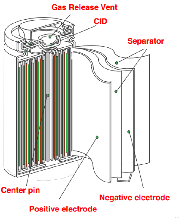
just came across some info, not sure if discussed here already,
seems some 18650 cells have an auto disconnect under the caps, very simple and clever design, once the cell
gas level reaches a certain level the cell cuts off the pos connection.
this video explains very clearly how it works
' https://www.youtube.com/watch?v=1w3Tv1Jg0ps '

You can also reverse the cutoff.
 
most if not all cells from reputable brands have this basic feature. this is also why you should not solder them because the plate is triggerd by heat causing the resistance to rise.
 
I had no idea 18650 cells had the CID feature and also a PTC ring. CID being the pressure type fuse ( dome shaped plate) causing cathode disconnect, and PTC being a polymer/carbon ring that changes resistance with temperature ( another type of fuse but resets when temp drops back down)( the annular ring just under the top cap).
These cells have been well developed indeed.
I'm wondering if a small visual aid could be used to show that the pressure plate has been popped, aiding in repairing packs or identifying which cells have had excessive gas formation, for example just a small piece of the CID plate could extend out ( or near) one of the top holes ( of cathode) or just give some indication to the outside world that the CID has popped.
That probably wouldn't be hard to do for manufacturers to do and would certainly aid pack repair.
 
replacing cells usually needs to happen in bulk. if there is a reason why one or more cells popped their lids you cannot trust the other cells in that parralel string anymore and they need to be replaced as well.
 
Interesting thread. Thanks for sharing.

flippy said:
most if not all cells from reputable brands have this basic feature. this is also why you should not solder them because the plate is triggerd by heat causing the resistance to rise.

I thought this plate is triggered by pressure only?
If so, than soldering should be no problem (given that it's done right with high end soldering equipment).

Does anyone know more about mentioned PTC fuses?
From my experience a Samsung 25R for instance doesn't have such as it turned into a rocket propulsion when i intentionally shorted the top cap with the shell (just to see what would happen).
 
madin88 said:
Does anyone know more about mentioned PTC fuses?
From my experience a Samsung 25R for instance doesn't have such as it turned into a rocket propulsion when i intentionally shorted the top cap with the shell (just to see what would happen).

Sounds about right. A long time ago I purchased some Sanyo cells and asked the vendor about the PTC fuses, he told me they didn't have them. I would not assume all cells have these PTC fuses.
 
its the same thing. pressure is a result of heating the cell. often (see: panasonic) the disk basically slowly melts or bends when you heat it up so it lowers the pressiure it keeps on the tab increasing the resistance. that basically compounds of time. you can see this happen in solderd packs that despite being made of new matched sells from the same lot need quite agressive balancing in order to keep it in line.
it wont kill the pack but it will reduce its quality and lifespan.
the disks in samsungs are almost impossible to trigger with the usual rocket-type events mentioned. panasonics on the other hand tend to just leak and smoke a bit and fail a lot less dramatically. i got 3 leaking over my bench right now because i had too much pulse time on the welder and punctured them. they just ooze a bit of liquid (really bad stuff) and nothing more. with soldering all the cells would be damaged because of heat.

and this is why you should not solder them. and its dumb to not spend 80 bucks on a welder when you have a 1000 bucks worth of cells.
 
Yes and no. Protected cells have a second protextion purely based on current wich makes them slighty taller and usually resets after they cooled down. This is separate from the pressure/heat based "last resort" that all cells have and need much more abuse to rupture.
 
madin88 said:
Interesting thread. Thanks for sharing.

flippy said:
most if not all cells from reputable brands have this basic feature. this is also why you should not solder them because the plate is triggerd by heat causing the resistance to rise.

I thought this plate is triggered by pressure only?
If so, than soldering should be no problem (given that it's done right with high end soldering equipment).

Does anyone know more about mentioned PTC fuses?

PTC actually means. POSITIVE TEMPERATURE COEFICIENT.
It refers to a polymer disc that changes resistance at high temperature... Usually about 130 C... In order to protect against high current discharge situations ..specifically a external short.
It functions on a "phase change" principle , in that the increase in resistance is quite sudden at the specific temperature,...and is reversible !, ..IE:- as the PTC cools back down below that phase change temperature, the resistance reduces to its original level.c
Soldering to the top cap (if done correctly,)...will not irrepairably harm the PTC device.
Read more from NASA ...
https://batteryworkshop.msfc.nasa.gov/presentations/02_Cell%20PTC%20Characterization_EDarcy.pdf
 
Great article spinningmagnets.

flippy said:
the disks in samsungs are almost impossible to trigger with the usual rocket-type events mentioned. panasonics on the other hand tend to just leak and smoke a bit and fail a lot less dramatically. i got 3 leaking over my bench right now because i had too much pulse time on the welder and punctured them. they just ooze a bit of liquid (really bad stuff) and nothing more. with soldering all the cells would be damaged because of heat.

Most cells will just ooze out the electrolyte if they got leaky due to a mechanical damage (if not shorted).
In my case this happenend with many different cells like you mentioned if the welder punctured them, or when i was pulling off already welded tabs from older batteries.
No fire, No heat, just electrolyte that comes out.

Most of the DIY welding also leads to very high heat that reaches the inside of the cell.
Try to weld two metal strips onto each other (same thing as if you would weld on the can of an 18650), and than take a look on the bottom side.
The color changed from shiny metal to somethig like dark blue or grey, so 400-500°C?!
Or do the same with the metal strips lying on a plastic surface (there is a plastic disc in the can as insulator). The welder will melt the plastic, soldering not.
This meand that welding leads to much higher peak heat inside the cell, while soldering leads to longer lasting heat but not so high.
 
welding leads to a highly localized peak. that is no problem for the cell to absorb. the cell contact are also welded inside the cell. you wont damage the electrolyte. the plastic disk is on the positive side wich "floats" above the disk. no heat during welding gets to the disk. the bottom (usually) does not have a disk because that is the place the negative is connected to.

there are many reason why welding is the superior choice that makes for a really long topic, but in short: if soldering was the superior option it would be done industrially. it is also the recommended way by all cell manufacutrers, in a lot of (extended) datasheets they often warn against soldering.
 
flippy said:
welding leads to a highly localized peak. that is no problem for the cell to absorb. you wont damage the electrolyte. the plastic disk is on the positive side wich "floats" above the disk. no heat during welding gets to the disk. the bottom (usually) does not have a disk because that is the place the negative is connected to.
I am not talking about the positive side or the CID / PTC. I am talking about what happens if you weld on the can.
IMO the most critical area when welding or soldering because the heat will directly "touch" the electrolyte; not so on the positive pole.

There is a plastic washer on bottom and top of the rolled foil which function as insualtion, and this disc could suffer damage when welding so the peak heat reaching the inside must be huge!

take a look at this pic from spinningmags article:
Cells21700_2.png


there are many reason why welding is the superior choice that makes for a really long topic, but in short: if soldering was the superior option it would be done industrially.
Yes soldering makes no sense industrially.
I don't say soldering is better than welding, and for 95% of the batteries i build i use the the welder (if it can be welded, i will weld it), but i noticed DIY welding leads to much higher peak heat to the elelctrolyte (which is on all surfaces inside the cell).
The question is if this peak heat adds damage to the cell or not. I believe the electrolyte could vaporize at this area.
 
As long as the heat doesn't decompose the electrolyte, it will condense and turn back into liquid if vaporized. Melting the plastic insulators is the real thing to worry about.
 
flippy said:
most if not all cells from reputable brands have this basic feature. this is also why you should not solder them because the plate is triggerd by heat causing the resistance to rise.

Its worth noting that genuine "Tesla" 18650 cells (sourced from actual car traction packs)... DO NOT have either CID or PTC devices incorperated.
They do have a different type of pressure vent system to prevent violent depressurisation
 
Hillhater said:
ts worth noting that genuine "Tesla" 18650 cells (sourced from actual car traction packs)... DO NOT have either CID or PTC devices incorperated.
They do have a different type of pressure vent system to prevent violent depressurisation
they have a single use burst plate. something all cells have. but they dont have or need further protection as that is done by the fuse wire and the BMS and that special anti-lithium-burning-goo they plasterd the battery with.
taking those cells out of their original holder does mean you need to compensate for the loss of the fuse wire.
 
Back
Top