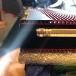
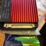
What eee291 said. A 48 volt Ping battery will have a 12 pin connector, (the same as is used for the 36 volt battery), plus a 4 pin connector, plus the bms gets its last negative from the main negative connector that goes to the BMS.
Your package has a 21P on it, but based on my experience with Ping batteries they are manufactured with 2, 3, or 4 cells in parallel (which determines that the battery will be 10, 15, or 20 AH, and then 12, 16, or 17 of these sub packs are connected in series which results in a battery being 36, 48, or 52 Volts. And then the corresponding number of sense wires run to the series connection points. I may be off base here, but I doubt you are connecting 20 cells in parallel and then trying to connect the same cells to a bms via 21 sense wires because all 20 cells would be connected to the same positive and to the same negative and as long as they are connected in parallel you can't measure the individual cell voltage separate from all the other cells it is connected to in parallel. So it seems to me you must have a 21S bms not a 21P bms?


