Anyone dealt with Tech Direct Inc. LG Chem Modules

I have, kinda.

I got the 36V 30Ah 10S 2P from Monstarr on this forum.

You can also look up Jehu Garcia on Youtube, he's dealt with these cells before, even though he can be a bit clueless at times.

Also the price is pretty decent.
 
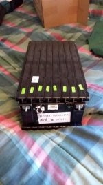
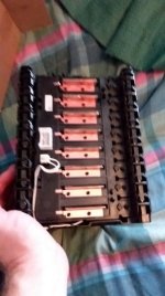
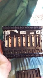
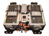
I have bought from TechDirect twice. Both times it was for those modules. Everything went as expected. The modules have worked out great. My last shipment was all 2016 and newer modules. They are from a Chrysler Pacifica Hybrid minivan. They are just like Chevy Volt cells. The case is high density plastic with a heat spreader between cells just like a volt battery. The case of the module is mostly rigid. There is some movement between cell holders from the click together type design. When installed on the Pacifica the battery modules sit on a cooling plate that cools the heat spreader, thus the cells. The modules have integrated compression from the honeycomb sides. I am not sure if there is a BMS board installed on the modules or not. There is two main BMS controllers as seen in the pics. So I am thinking there is not a bms inside the module. I know that the pins of the BMS connector have all the cell voltages and the one, two, or three temp sensors that are attached. I have seen three different versions of the BMS connector. This battery might also be used in some European cars like the Volvo Xc90 T8. The voltage curves are the same as the Chevy Volt and other LG Chem pouch cell batteries. I have a 96s4p solar battery setup. 24 modules in all. I soldered bms wires to the cell ends and made my own BMS harness. I had to use a 75watt iron. The copper tabs for the cells absorb heat really well. The front and the back of the battery has access to the pouch cell tabs. The front has 1,3,5,7,9.... and the back has 2,4,6,8...
Anyways, I hope that helps.
-YS

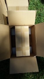
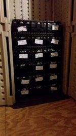
Attached is my pictures from the first shipment.
 

Attachments

  • 20170906_095635.jpg
    20170906_095635.jpg
    46.3 KB · Views: 4,478
  • 20170906_101642.jpg
    20170906_101642.jpg
    52.9 KB · Views: 4,478
  • 20170906_101920.jpg
    20170906_101920.jpg
    52.3 KB · Views: 4,478
  • 20170906_102057.jpg
    20170906_102057.jpg
    51.3 KB · Views: 4,478
  • 20170907_005450.jpg
    20170907_005450.jpg
    39.8 KB · Views: 4,478
  • 20170907_102837.jpg
    20170907_102837.jpg
    48.4 KB · Views: 4,478
  • images.duckduckgo.com.jpg
    images.duckduckgo.com.jpg
    61.6 KB · Views: 4,478
here is a link to YouTube of a guy taking apart a complete battery pack from the Chrysler Pacifica Hybrid. https://youtu.be/7jAO8dqBbSo [youtube]7jAO8dqBbSo[/youtube]
 
Great info here, thanks yewsuck. I'm about to pull the trigger on 4 of these bricks from TechDirect. Does anyone else have any feedback? Do we know the pinout on the BMS socket? I'd like to use the existing connections for cell-level monitoring.
 
I just received two of these from Tech Direct, placed the order via their website instead of Ebay. No major issues, one of the modules had one of the plastic brackets cracked but without any other visible damage. Wired them up into the EV and it works fine.

It would be nice to use that BMS connector, but my search didn't come up with the make/model. Tech Direct does sell salvaged wire harnesses, but I think $25 + shipping is a bit too much so can't convince myself to buy them :D
 
Sweet, I'm glad they worked well for you. Do you have a link to your EV? I'd like to see how much space these really take up.
I agree, $25 is too much for the chopped wiring harness especially since we still won't know which wire is which. I'll do some digging on the Chrysler forums to see if anyone has info on the pins & the connector type.
 
I shoved them into Polaris Ranger EV instead of the four 155Ah lead-acid batteries on each side. This module isn't as tall as those FLA batteries, but is a bit wider/longer.

cHr1STooPfXYbnl072bA_eN3qaT2vyeg7waZVBnhtxc-fXSqir_09Qm4weSmyaJiM6aQaqvEKwQfTvDxVGRs55zF9pTG5cSijOFG0xAIpC7VsC70rQ2QK-GbKdxJnABjlTXD-kVy-LzokTCGTRBPFWXqWxd5IQN05UIcYShcYfXdMIzf0kc7bxNRH4tROFM-oQBZ-32eHAphTKKaiMVclpFR_zIZk6GKPscSfKO7zQ7NBUX4N4LuoVwUzPSIVN9dP1ITkRs6B-k6bNW7aXK-uuf77TpJnD_4JNQzutbBAs8cHbQ1VqDSud4AL15kKgxT9zZzXq1CIcw8o3XIwjQLY6uh2_rndcGFd0zQr3pjoRPqjZAdcEBw7IJekLxj13C-6cUSJaV2vFg_-g83p7yy9lVSOQZQdkD2bs_I9Z_5EQd9RhyRwUGDjAtKlRqIDUdQXNU7E2pfh354gCYMETxhyr0YlZWOGc4kGDROuxnCu3wgxO71XQM5KBujyWhbhQ3xi1YXK0BotLCgyxGuKA46gyQh4QrLEdU8is0fnc_Tv3uflcJB3Fg4UJV31cKG7RqQx1c4uWpTn6N5HSVe1tfZuw9rwrB0JhkTRiOhEvOt8cqdtrhfQqirWwjuggAUZmF5Yp1JDpQ1qd9nGTiUBdrmeS1YVmDP_SUZun2kGfGOzv_meiWisOOfG79Mqj4ZVXxRuy_veRn8mXqZ3uSXzWo=w1678-h1258-no
 
Mandres said:
I agree, $25 is too much for the chopped wiring harness especially since we still won't know which wire is which. I'll do some digging on the Chrysler forums to see if anyone has info on the pins & the connector type.

I reached out to Tech Direct, $25 is for a pair of those cables. I think the issue there could be that one connector serves only half of the cells and a bunch of temp sensors, and connector on the opposite side does the other half. I originally thought it has some kind of pass through purpose instead, and then there is another smaller connector for a single temp sensor. So if you take that into account, maybe it's not that much money for a pair of prewired connectors :)
 
cricketo said:
I reached out to Tech Direct, $25 is for a pair of those cables. I think the issue there could be that one connector serves only half of the cells and a bunch of temp sensors, and connector on the opposite side does the other half. I originally thought it has some kind of pass through purpose instead, and then there is another smaller connector for a single temp sensor. So if you take that into account, maybe it's not that much money for a pair of prewired connectors :)

Does anyone have any documentation on the pin-out. Which ones are for which voltage and which ones are for a thermistor and how many are there and their locations?

Just a simple document with the pin-outs would be great even if it did not have the locations of the temps.
 
palmer_md said:
Does anyone have any documentation on the pin-out. Which ones are for which voltage and which ones are for a thermistor and how many are there and their locations?

Just a simple document with the pin-outs would be great even if it did not have the locations of the temps.

I couldn't find the pinout doc for these modules. I ended up getting the wiring harnesses from TechDirect, but I haven't traced them yet. Lots of wires... also connectors are different between front and back.
 
I just purchased 12 of these batteries...

does anyone have an opinion on the best BMS to use for these?

yewsuck - which BMS did you use in your setup?
 
I use a bms from Chargery. However your needs may be different. How you use the batteries will determine what you need.
01. How are you using the batteries?
02. How are you connecting the 16s battery modules together to form your final pack?
03. What is the average and the maximun current draw of the final battery setup you are making?
04. What is the charging device you are going to use and what is the max charging amps? Also, does this charging source have a c-rate cutoff, meaning does the charger turn itself off when charge voltage is met or does it just keep the battery at max voltage and countiously charges?


------Example 1------
01. I am making a stationary battery pack to power an inverter for powering my house.
02. I am connecting my 16s modules in a 96s4p. Configured as a four modules in paralel set seriesed 6 times. Which would be a 402.3vdc and 180ahr pack. About 355vdc nominal.
03. My max current draw is 60amps with 15a being average.
04. I will be charging using a solar controller that will stop charging and monitor the voltage. This charger will automatically start and stop charging as required.
--------------------------

------Example 2-----
01. I am also making a stationary battery pack to power an inverter for powering my house
02. I am connecting my 16s modules in a 16s24p. Configured as all modules in paralel set. Which would be a 67.2vdc and 1080ahr pack. About 59.2vdc (3.7x16)nominal.
03. My max current draw is 350amps with 90a being average.
04. I will be charging using a meanwell power supply that is Cc/Cv and does not stop charging and will keep my batteries at max voltage as long as the charger is connected.
--------------------------

Okay.... I would recommend very different BMS units for these two examples based on the current, voltage, amperes, and saftey requirements.
In the first example i would simply use a seperate cheap chinese 16s bms rated for about 60 amps max for each module. As in, each battery module would have it's own BMS.
In the second example i would go with a single 16s BMS like the Chargery BMS16T or any other BMS that does not use Mosfets and instead uses or controls relays. Most Mosfet based bms's do not go above 100 amps max rating. And if they do... they are expensive and get very hot. In this example we need to over current control a possible 350 amps. Also the charging circuit is not regulated to protect the batteries so much. It might be good to have a bms that can (using a relay in this case) turn off the charging sources.
I actually have my battery configuration close to example one. My BMS solution is close to Solution two. Why, you might say? Because i wanted the option of having both configurations. If my high voltage inverter fails i can always reconfigure my batteries by swapping a few wires and i can use a lower voltage inverter. This made for more expense in the BMS deparment. But it is what i wanted and needed. What you want and need will depend on the factors you set.... we do not know those factors yet, so we really can not help you. Let us know what you are doing and we can help. Take care.

-YS
 
VERY IMPORTANT INFO MISSING IN THIS PACK DESCRIPTION
Are those modules brand new?
if from wrecked car, at very least what production year??
yes looks like VOLT gen-2 uses same cells.
 
Is this the same company that was selling Leaf modules that only had ~50% of original capacity? In general the industry deems anything in the 70-80% of original capacity range to be end of life (EOL). So you shouldn't buy anything like that.

What capacity were the cells originally and what is their capacity now?
 
These Modules are Used... original voltage: 60.8 (3.8V/cell).
Voltage now averages about 59V.

I would like to put these in an EV.
I plan on a series parallel configuration. 6 in series for 360V in parallel with another 6 to increase the Ahr from 40 to 80Ahr. it will be used with a Siemens 5W13? motor (Ford Electric motor). I'll use a RMS DX100 capable of 300Arms continous (regen will be used). I'll also be using a PFC30 30A charger.

I would like to balance charge these to ensure all cells are charged before evaluating the capacity. Capicity should be 90% (we will see what the actual is...) I may end up picking the best 6 and just running with a 40Ahr system.
I would not want to trip the charger when one cell reaches the max. would that eliminate the relay system?
or does the relay system burn off excess current like the mosfet system?

I am rather new to BMS systems. I understand the theory but not necessarily the product key words that are used.
 
Lonewolf said:
I would like to balance charge these to ensure all cells are charged before evaluating the capacity. Capicity should be 90% (we will see what the actual is...) I may end up picking the best 6 and just running with a 40Ahr system.
Yes you would want to balance charge and find your true capacities. You will probably want that extra battery pack for extended range. I woukd definetly design the extra pack into your system as a option if needed. Just remember that you should keep batteries within or less than 1 volt when making the connections of parallel batteries.

I would not want to trip the charger when one cell reaches the max. would that eliminate the relay system? You may or may not have a choice in this matter. The BMS's job is to protect the battery as the last satety to prevent battery damage and battery fires. Not for normal control of charging/discharging. Most balancing systems included in BMS's only do between 66mah (0.066 amps) up to about 1.2 amp hours. If your chargier is at a rate above the balancing amps then a high cell will keep being charged and be over charged. Example: I have one cell at 4.2vdc and my BMS starts balancing that cell at 1 amp of bleed off. My charger is 5 amps. I am now charging the all cells at 5amps except the high cell which is being charged at 4 amps. All cells continue to rise in voltage. One thing you can do is set the balancing voltage to 4.2 and set the charger disconnect to 4.30vdc... or set both lower for better battery longevity. This would activate the balnacing while allowing the other cells to continue to charge... up to a point. Your BMS will continue to balance any cells that are in a high state above your balance voltage setting regardless of your charger being on or off. Also a good battery pack that is designed properly for the load of the system will not go out of balance very easily. You should not be needing to balance a pack often. Balancing should be only to fix the little, as in tiny, internal resistance differences of the cells that are from manufacturing tolerences. BTW, Above voltages are just for example only... LgChem says these batteries are full at 4.15vdc. So i would not charge above that. LgChem also says to normal charge at 0.3 of capacity and limited use fast charge is 1c. Max charging voltage of 4.3vdc and a remove from service overvoltage of 4.45vdc. A remove from service undervoltage of 2vdc.

or does the relay system burn off excess current like the mosfet system?
I am rather new to BMS systems. I understand the theory but not necessarily the product key words that are used.
The Relays or Mosfets are simply there to disconnect the main output of the battery if any cell goes above or below a max limit. It simply removes the battery from charge and discharge sources to prevent battery damage. All monitoring of individual cells and balancing is a seperate function of the BMS. You have your main battery high amp leads/wires for main power (350vdc) attached to the main output positive and negative. You also have your smaller thinner balance leads/wires for monitoring of individual cells (3.7vdc) and balance of said cells.

Again... the BMS's job is to be the last defence for protecting the battery as a whole and the individual cells. This could posibly any of the following:
Overvoltage/Undervoltage protection of individual cells
Overvoltage/Undervoltage protection of the pack as a whole
Balancing of the cells using passive resistors or active cell to cell balancing
Over current protection
...and so on. How it accomplishes these task can be different such as the relay/mosfet systems. BMS complexity can range from simple proctections all the way to first class complex production auto systems.

At this point i would start a new thread or topic on this forum to ask about what BMS you would need for your setup. This topic is about the batteries themselves. You will get much more advice and questions answered if you make a new topic.
In the new thread you can discuss your needs and what you are doing... and have athread for your progress of your build! :)
-YS

 
Since the copper bars are accessible shouldn't it be possible for me to charge this as two separate 8s packs with my hobby charger? I'd add two sets of 8s balance leads and a charging connector to cells 1-8 and another charging connector to cells 9-16.
 
Sure, your connections would look like mine. I have two 8s connectors that i soldered to the cells. The connectors and cells on the module are arranged as 1,3,5,7,9... on one side and 2,4,6,8... on the other. So you would have two 8s "Y" harnesses. Do note that the cells are hard to solder to with oit a very large soldering iron. I used a 75 watt and had some success. Those big copper ends are prone to cold solder joints if you rush it.
-YS
 
I haven’t dealt with them for LG chem, but I bought 14 leaf modules from them in March and finally got to the point of getting my motorcycle rideable only to find out the “7kwh” pack is only useable to about 3700wh. I’m very suspicious that they sold me more like 50% capacity batteries rather than the 75%+ listed on eBay.

Since it was over 180 days ago and they’ve been in and out of the pack (no longer aesthetically new looking), I’m not really sure what to do. The current range with these is about 1/2 what it sounds like other people with fresher batteries are getting.
 
There is nothing you can do. You can't wait that long to file a claim.

I also believe I bought bad batteries from Tech Direct. I bought their 20ah Panasonic Lithium batteries. One has completely failed and the others don't even reach 20ah. I bought 5 more from used cells greentecauto and they hit 24ah (which is new spec) and they are not bloated like the cells I bought from Tech Direct. Had I known more about those cells when I first ordered them I would have immedately returned them back to Tech Direct. I paid $17 a piece from TD and $20 a piece from greentecauto so it's not like I saved much going with TD. I'm running my LG Chem battery I got from them through some cycles now and if it shows bad signs I'm returning it since I have only had it a few days.
 
Back
Top