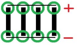
Cell level fuses?

rg12

100 kW
Joined
Jul 26, 2014
Messages
1,591
Hey guys,

Been researching 18650 cell level fuses and theres something I don't get or more like missing I guess.
https://www.google.co.il/search?q=1...#imgdii=kXMERf-WlEX_5M:&imgrc=fxEFTXlvWvxYzM:
I see a busbar with two rows of cells on the sides of it and each set of two cells is soldered with a fine wire to the busbar.
First of all, where are the serial connections? I don't get whats going on here...
Are the fuses just for the parallel connections? because there is no way to transfer high current through those hairs.
and what happens if one cell goes bad? what is the benefit? what scenario can cause the higher current to be pulled from the cell so the fuse will burn?
I don't see how a case of a cell dying would burn the fuse and avoid pulling all of the parallel cells down...
 
In the picture you linked, it looks like the bus bar is soldered at one end, I assume this is where the series connection is made. Yes, the fuse wires are only for the parallel connections, to connect each cell to to the bus.

This style of fusing gives you some protection when a single cell develops an internal short. In this situation, all the rest of the cells in the parallel group will be putting current into the shorted cell. This should result in a high current flowing into the shorted cell, which breaks the fuse wire.
 
Addy said:
In the picture you linked, it looks like the bus bar is soldered at one end, I assume this is where the series connection is made. Yes, the fuse wires are only for the parallel connections, to connect each cell to to the bus.

This style of fusing gives you some protection when a single cell develops an internal short. In this situation, all the rest of the cells in the parallel group will be putting current into the shorted cell. This should result in a high current flowing into the shorted cell, which breaks the fuse wire.

but what if the cell doesn't die instantly? it's mostly gradual...
fuses.jpg
What about a scenatio where one of the cells in the photo goes bad, it is not only connected in parallel to the negative row but it's connected also to the next negative cell (parallel) through the next serial connection (positive)

I use a bus bar on the whole first and last parallel groups and solder the main wires to the busbar for even current distribution.
It seems to not make sense since the busbar is a thick copper piece conncted to all of the cells in parallel so they will always be connected together.

Also, I see in this video (minute 14:00): https://www.youtube.com/watch?v=oNfTEHBz_bg
that em3ev uses fuses on the bms balance wires.
So same question, what short can be a problem that these fuses would be needed? the balance wire is connected to a whole parallel row.
So it brings another question: would those balance wire fuses be needed on a cell level fuse type build? and if so, wouldn't a cell going bad next to the balance wire cause the bms to lose connection with the rest of the cells in parallel?
 
Yeah, if the cell is only slightly damaged, it could just slowly drain the parallel group.


rg12 said:


I use a bus bar on the whole first and last parallel groups and solder the main wires to the busbar for even current distribution.
It seems to not make sense since the busbar is a thick copper piece conncted to all of the cells in parallel so they will always be connected together.

If you want to do individual cell fusing, you can't really do it if you're making multiple connections to each cell. The fuse wire should be the only path for current to flow in/out of a cell. If you have multiple paths for current to take, how do you know how much current is going through the fuse? This also defeats the purpose of the fuse, if the fuse breaks and the cell is still connected somewhere else.
 
Addy said:
Yeah, if the cell is only slightly damaged, it could just slowly drain the parallel group.


rg12 said:
fuses.jpg

I use a bus bar on the whole first and last parallel groups and solder the main wires to the busbar for even current distribution.
It seems to not make sense since the busbar is a thick copper piece conncted to all of the cells in parallel so they will always be connected together.

If you want to do individual cell fusing, you can't really do it if you're making multiple connections to each cell. The fuse wire should be the only path for current to flow in/out of a cell. If you have multiple paths for current to take, how do you know how much current is going through the fuse? This also defeats the purpose of the fuse, if the fuse breaks and the cell is still connected somewhere else.

Yes, thats what I didn't get.
So those powerwalls have so many cells in parallel that they can transfer the current through that hair of a conductor, so the question is if it can be done somehow with an 8P pack that gets like 120A pulled out of it (I'm dealing with mostly high powered ebikes)
 
You'd have to select an appropriate wire gauge for the fuses. 120A out of an 8P pack would be 15A per cell, so your fuse wire should be able to pass 15A comfortably. You should also consider how much resistance the fuse wire will add to each cell. If your fuse wire gets hot under normal use, that heat is going into your cells and wiring. In that situation it's probably not worth it to have fuses.

This style of fusing is better suited to battery packs that don't push individual cells very hard.
 
Addy said:
You'd have to select an appropriate wire gauge for the fuses. 120A out of an 8P pack would be 15A per cell, so your fuse wire should be able to pass 15A comfortably. You should also consider how much resistance the fuse wire will add to each cell. If your fuse wire gets hot under normal use, that heat is going into your cells and wiring. In that situation it's probably not worth it to have fuses.

This style of fusing is better suited to battery packs that don't push individual cells very hard.

Why would a parallel connection need to carry the same load as the serial connection?
 
https://endless-sphere.com/forums/viewtopic.php?f=14&t=93297

I use cell level fuses on all my packs. I do use recycled cells and my packs so far have not been high amp applications.
The small fuse wires never get above ambient temperature.

I'm currently building a 14s5p 25R pack for my Lightningrods small block motor, the fuse wire is rated 15 amp.
 
rg12 said:
Addy said:
You'd have to select an appropriate wire gauge for the fuses. 120A out of an 8P pack would be 15A per cell, so your fuse wire should be able to pass 15A comfortably. You should also consider how much resistance the fuse wire will add to each cell. If your fuse wire gets hot under normal use, that heat is going into your cells and wiring. In that situation it's probably not worth it to have fuses.

This style of fusing is better suited to battery packs that don't push individual cells very hard.

Why would a parallel connection need to carry the same load as the serial connection?

If you have a fuse wire on a cell, it should be the only path for current to flow, which means it is carrying it's share of the pack's total current.
 
Addy said:
rg12 said:
Addy said:
You'd have to select an appropriate wire gauge for the fuses. 120A out of an 8P pack would be 15A per cell, so your fuse wire should be able to pass 15A comfortably. You should also consider how much resistance the fuse wire will add to each cell. If your fuse wire gets hot under normal use, that heat is going into your cells and wiring. In that situation it's probably not worth it to have fuses.

This style of fusing is better suited to battery packs that don't push individual cells very hard.

Why would a parallel connection need to carry the same load as the serial connection?

If you have a fuse wire on a cell, it should be the only path for current to flow, which means it is carrying it's share of the pack's total current.

Yeah so I guess there is no way I could use that since I only look to add more conductivity (copper etc) in the serial connections.

What about the bms wire pico fuses? for what scenario are they used for?
 
rg12 said:
Addy said:
rg12 said:
Addy said:
You'd have to select an appropriate wire gauge for the fuses. 120A out of an 8P pack would be 15A per cell, so your fuse wire should be able to pass 15A comfortably. You should also consider how much resistance the fuse wire will add to each cell. If your fuse wire gets hot under normal use, that heat is going into your cells and wiring. In that situation it's probably not worth it to have fuses.

This style of fusing is better suited to battery packs that don't push individual cells very hard.

Why would a parallel connection need to carry the same load as the serial connection?

If you have a fuse wire on a cell, it should be the only path for current to flow, which means it is carrying it's share of the pack's total current.

Yeah so I guess there is no way I could use that since I only look to add more conductivity (copper etc) in the serial connections.

What about the bms wire pico fuses? for what scenario are they used for?

As far as I know the pico and glass axial fuses only come in low amp rating
 
EbikeAus said:
rg12 said:
Addy said:
rg12 said:
Why would a parallel connection need to carry the same load as the serial connection?

If you have a fuse wire on a cell, it should be the only path for current to flow, which means it is carrying it's share of the pack's total current.

Yeah so I guess there is no way I could use that since I only look to add more conductivity (copper etc) in the serial connections.

What about the bms wire pico fuses? for what scenario are they used for?

As far as I know the pico and glass axial fuses only come in low amp rating

Was talking about fusing the balance wires not the cells:
"Also, I see in this video (minute 14:00): https://www.youtube.com/watch?v=oNfTEHBz_bg
that em3ev uses fuses on the bms balance wires."
 
Back
Top