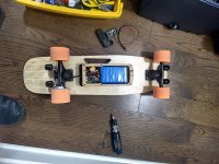
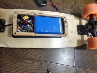
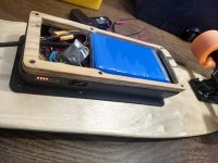
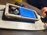
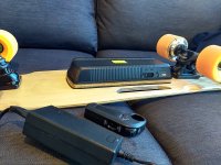
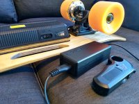
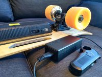
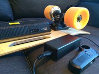
FIX for non trimmable Li-Ion charger that slightly overcharges eSkate

Matador

100 kW
Joined
Jun 29, 2016
Messages
1,045
Hey there. Quick question for you folks.

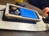
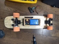
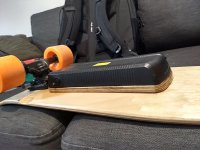
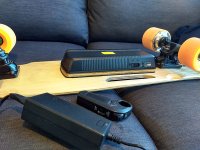
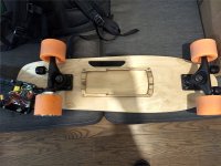
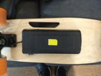
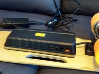
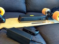
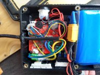
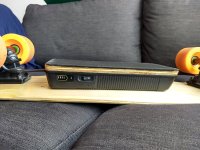
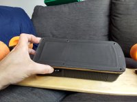
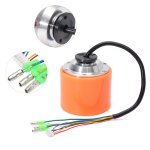
I have a cheap e-skateboard called the "Small Fish Plate" (mono hub motor 250W). It runs on a 7S1P Lithium cobalt oxide battery (cells are cheap chinese BFN 2000 mAh). The fun kicktail skateboard weights only 9 pounds, is easy to carry to work and tops out at 18 km/h. That's great for my 2.1 km commute to work in downtown Toronto. Charges from 30% to 100% in a hour or so... Here's a vid presenting the thing and it's guts: [youtube]GYS726Gx3fk[/youtube]

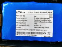
But no surprise here, the battery gave out after just one month (I expected that, but had some spare quality cells to use and rebuild...). So I rebuilt a battery. A more robust battery. The controller peaks at around 10A max. So that was a bit hard on that cheap chinese BFN 7S1P 2Ah battery (chinese cells each had around 52 mOhm DCIR, exept the one dead cell which was above 1000 mOhm DCIR). On the original battery, there is no real balancing BMS, just a protective 7S 15A-PCB (LVC and HVC cell monitoring).

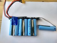
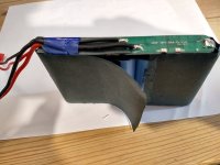
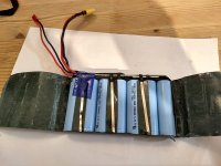
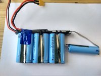
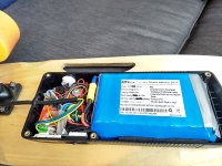
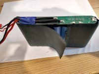
This was the old battery (7cells only ! Hard to believe it but while it worked, I onced did 4.8 km before it died...):View attachment 11Old battery.jpgOld battery 2.jpg
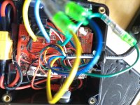
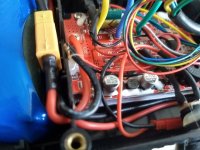
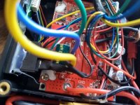
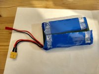
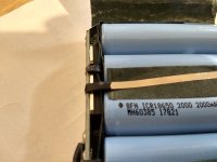
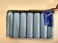
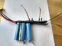
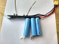
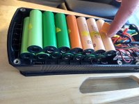
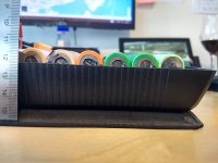
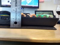
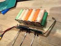
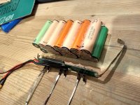
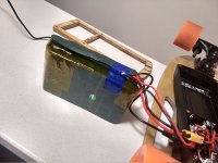
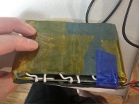
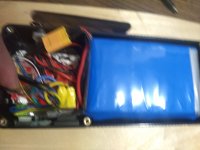
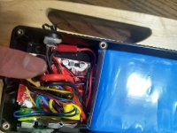
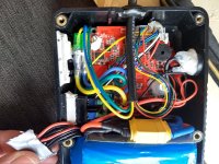
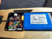
So I built a 7S2P battery from recycled dyson battery packs that had faulty BMS (one had 6 Sony VTC4 (2100 mAh NMC, max 30A, 23 mOhm), one had 6 Samsung HD2C (2100mAh NCM, max 22A, 22 mOhm), and also used two LG MH1 (2150mAh, LCO, max 10a, 42 mOhm). I transplanted the protective PCB on the new battery. Of course I balanced all cells to 0.01V before paralleling. Pictures: View attachment 8Grafting bms.jpgView attachment 6New batt 2.jpgNew batt 3.jpgNew batt 4.jpgNew batt 5.jpg
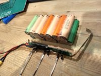
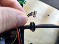
Even though there is a protective PCB, I did attach some manual balance leads with a JST connector to new bigger battery. Just to check cell voltage once in a while.

Well guess what. The original 7S 2A charger (I did not suspect) overcharged the battery to 29.65V (4.236V per cell) instead of stopping at 29.4V (4.20V)... I worried about poor cycle life...

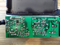
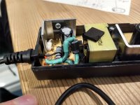
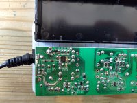
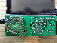
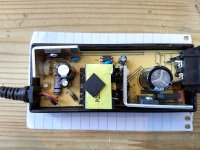
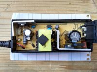
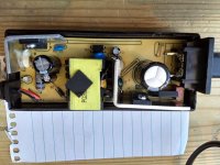
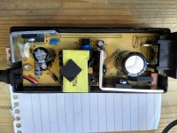
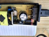
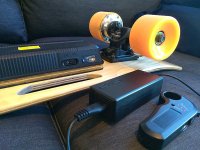
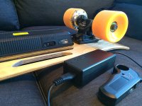
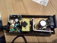
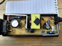
So I opened up the charger... But there is not trim pot at all in it. So I bought a Schottky diode. More specifically it's a 5A capable Vishnay IR 50SQ100 diode (datasheet: https://www.mouser.ca/datasheet/2/427/Vishay_50SQ060,080,100(M3)-1-1211393.pdf).Charger front.jpgCharger back.jpg
THE QUESTION:
Can I just connect the diode at the charger's output and hope it will reduce voltage (slight voltage drop) enough to bring cells below 4.20V fully charged ???
Charger output on full cells is currently 29.65V. I would like the charger to terminate at 29.40V and stop.

There are no trim pots inside. I assume the charger is the usual CC-CV type.... and probably stops charging when reaching below 100 mA charge current, not sure (the LED turns from green to red when charging process terminates). I did check the datasheet graph showing foward voltage drop versus current for the schottky diode.
For the diode, voltage drop at 25°C is -0.55V@2A, -0.39V@0.1A, and -0.37V@0.05A. At higher temperature 125°C that voltage drop is a bit less : -0.42V@2A; -0.24V@0.1A; 0.21V@0.05A.
Since this charger usually become hot to touch, I assume temps will be sort of in the middle between 25°C and 125°C. So I assumed an average at 75°C : voltage drop would be -0.48V@2A; -0.32V@0.1A; -0.29V@0.05A.

So based on this I would be good. If charger cuts out below 100 mAh, I should get 29.65-0.32V = 29.33V at the end. But I'm worried about something.
Will the charger not cut out in the end because the voltage output will be lower ? Will I destroy the battery cells in the end for some reason ? I'm not worried about imbalance since the PCB does not balance anyways.

Will the fact that at 2A (at the begenning of the process of recharging the battery) the diode will cause a -0.48V drop on the output cause unreasonnably longer charging times ???

I'm hoping somebody has some insight on this diode method. Maybe i should just leave it as is and charge to 4.24V (I can't constantly monitor voltage when charging at work...).

Thanks in advance!

Matador
 
Your concerns are unwarranted.

1. The rate of charge won't be slowed substantially. Ohms law is I = v/r so for a 2 amp current, you could be charging at full rate with just a 2v differential and a 1 Ohm internal resistance battery.

With a half Ohm battery, you could still be charging at full rate with a 1v differential.

No idea what the internal resistance of your battery is, but usually they're measured in milliohm.

2. Most chargers don't actually stop charging. They simply provide constant voltage, and a light goes on when they detect a current is below a certain level. So when the battery voltage is close enough to the charger voltage, the battery effectively just stops taking power and obly the protection circuit and the diode is taking any power. Its possible that this will prevent the "full" light from turning on, but unlikely.

Go ahead and do what you planned. Though, to be honest, if cycle life was your main concern, I'd be dropping the final voltage even further. 3.95v per cell is the ideal, but that costs you nearly 20% of capacity. 4.1v per cell costs you only 5% but there are substantial increases there. There are graphs/tables for these things. Been a bit too long since I looked one up.
 
With that "Cocktail" of mixed cells, i would be more worried about getting an even charge on each 2p pair when charging.
Im guessing the charger is not a balancing charger ?
Might i suggest you invest $25 in a cheap RC balance charger that you can easily adjust the settings on , and ensure those mixed cells get an even charge.
I would also do a few cycles to see how evenly they discharge to low voltage .
 
Thanks for the reply Sunder.
I think I'll go ahead and try it.
I actually have two identical diodes.... Will start using one and see the result, but I could end up trying two diodes in series at the output. Cycle life is a bit of a concern, but not soo much, but 4.24V really seem to not give any advantage for the cycle loss. And I have fear of cell going over 4.22V... If imbalance results, I wouldn't want cells go further go out of whack and reach voltages even higher than the 4.24V I saw when bulk charging.

One thing I wasn't sure is if the charger doesn't reach the automatic volt cutoff where the LED switches to green, will it continue to apply a small trickled current instead of just cutting out for good (sortof like a BMS would do reaching HVC). I'm afraid in the end, if there is a constant trickle charge it might plate the lithium cell electrodes. Hence my questionning. But I'm not knowledgeble enough about how these type of charger really work. In my head, when the LED turns from green to red, I thought that meant the charger is triggered off, until it reaches a lower "release voltage" where it can restart to charge... I'm just speculating though.
 
Hillhater said:
With that "Cocktail" of mixed cells, i would be more worried about getting an even charge on each 2p pair when charging.
Im guessing the charger is not a balancing charger ?
Might i suggest you invest $25 in a cheap RC balance charger that you can easily adjust the settings on , and ensure those mixed cells get an even charge.
I would also do a few cycles to see how evenly they discharge to low voltage .

I have an Imax B6.... But this is 7S, so I do each seperately. I did manually balance each goups 3 times to get same voltage. I doesn't seem to drift after a two cycles, but I will check regularly...

each 2P string from 1S to 6S is one 2100 mAh Sony VTC4 paralleled to one Samsung 2100 mAh HD2C. The exception is the last (7th) S groupe which is made of two 2150 mAh MH1 cells. Some of the cells were rerapped, but here is the breakdown:

1.[VTC4 & HD2C]---2.[VTC4 & HD2C]---3.[VTC4 & HD2C]---4.[VTC4 & HD2C]---5.[VTC4 & HD2C]---6.[VTC4 & HD2C]---7.[MH1 & MH1]
 
I'll solder the diode after dinner.
Forgot to mention... this e-Skateboard cost me 145 USD shipped. I invested in more decent bearings though (Zealous bearings x 8 = 20 bucks) and a light system (25 bucks... the Koowheel lights). This new battery I made was essentially free. I knew the original would die soon enough. But all in all, buying these cheap components separatly (ESC, Motor, Trucks, Wheels, Battery, BMS, Charger, Decks, Grip tape, Risers, battery box, remote control) would of cost more if I was to buy everything seperatly...

It does not seem to be available from the seller I got it from at that time but I see an alternate seller who has the same one for just a tad more : https://www.ebay.com/itm/Electric-250W-15km-h-Longboard-Skateboard-Wireless-Remote-Control-Maple-Deck/292863472148?epid=3019509150&hash=item443005f214

Just got a funky griptape.
 
Sunder, I went ahead:Schottky diode1.jpg

Plugged it into the wall. LED green with no load (as normally expected).
No load voltage measured at 29.4V with newly installed schottky diode instead of 29.6V without.

Plugged the battery on. LED turned red (as normally expected when charging).

Schottky diode does become a quite hot, but nothing unbearable.
Started charging at 18h54 at 26.6V (or 59% or 3.80V/cells).
Now 19h26 and already at 28.5V (91% or 4.07V/cell).
Still charging.

Once done, will check terminal voltage, check if LED has change, and then, will measure cell voltage of every cell group (with charger still in the skateboard charging socket). We'll see how well this works if it does...

Matador
 
Alright, It works !
Terminal voltage is 29.35V hot (still) on the charger still plugged in but the LED did turn back to green.

Took from 18h54 to 20h04 to charge from 26.6V (3.800V) to 29.35V (4.192V). So that was 1h10 minutes.
LED did change back to green.

So I went from 26.65V (4.236V) without the Schottky diode to 26.35V (4.192V) with the Schottky diode.

I checked the voltage of each P groupes in series:
B1 - 4.18V
B2 - 4.18V
B3 - 4.20V
B4 - 4.20V
B5 - 4.19V (blinking to 4.20V)
B6 - 4.20V (blinking to 4.19V)
B7 - 4.20V

Minimally out of whack, but will follow every 10 charge cycles or so.

I would not do this with a standard silicone diode though, as I suspect it would get too hot (because higher voltage drop means more watts dissipated in heat) and would then need active cooling of the charger...

Experiment is a success.
Thanks for you guys help!

Matador
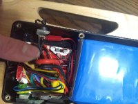
 
List of upgrades I did.

Bearing sucked right out of the factory. Changed for these : https://www.amazon.com/Zealous-Bearings-Skateboards-Longboards-Steel/dp/B00BL9VCRE/ref=sr_1_1_sspa?keywords=zealous+bearings&qid=1550985081&s=gateway&sr=8-1-spons&psc=1&smid=A26X9WNI6ZF0IL

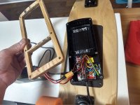
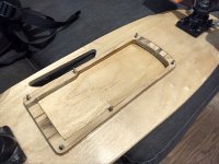
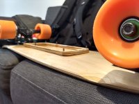
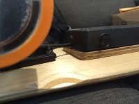
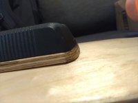
Made a gasket out of plywood. Got it waterproof by coating with epoxy.
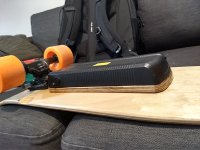
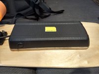
Had to by some additionnal adhesive foam for battery box: https://www.amazon.com/Homend-Neoprene-Adhesive-Multiple-Dimensions/dp/B07FPF26VW/ref=sr_1_fkmrnull_1?keywords=Homend+Sponge+Neoprene+With+Adhesive+Foam+Rubber+Sheet+1%2F8%E2%80%9D+Thick&qid=1550985231&s=gateway&sr=8-1-fkmrnull

Needed some longer M4-0.7 screws.... Used 35 mm to replace the original 25 mm, reason being the wood gasket + foam was 1.1 cm thick. Screws: https://www.ebay.com/itm/Stainless-Steel-M4-X-0-7-X-35mm-Phillips-Flat-Head-Machine-Screw-A2-PFH-10-Pack/181102690235?hash=item2a2a8fbfbb:g:hTUAAOxyTMdTNNAs:rk:1:pf:0.

Because of water, the switch died... This thing is not a normal switch, It's a momentary, normally opened switch. The chinease copycat switch is labeled KCD1-110, but I could not find the momentary switch "(On)-Off" version of it, so I bought the original brand, labelled as R6BBLKBLKFF from digikey.com, which is exactly the same dimension and is momentary : https://www.digikey.com/products/en?keywords=R6BBLKBLKFF.

I opted to rebuild my own battery because the original was too cheap. It can be bought off alibaba/aliexpress, but I will still die prematurely. Hence why I built a 7S2P battery instead of the original 7S1P configuration.

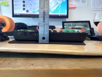
It still remains a very light eBoard at 9.6 pounds... Hard to bit for low weight, convienience of portability and short to medium range (around 6.5-9 km now, rather than the previous 3.5-4.5 km)
 
I've got a similar 48V charger that I just did this mod to it. I took a schottky diode and dropped it's 55V voltages down to 54.6 which is perfect for a fully charged liion battery. Only probablem is it charges at 1.7A which means my 1kw battery takes like 10-12hours to charge from empty.... I left the top off mine and instead put a volt/amp meter on it along with a small 40mm fan spinning at half its speed which makes it ultra quiet. 5V is perfect for the fan. Keeps it just cool enough to work great!!
32607377047_1406339c51_b.jpg
 
Just as a follow up. The BMS on this board is just a protective LVC/HVC PCB and does not balance charge.
So I measured separate cells voltage to check cell drift over cycles of my artisanal battery.
Here is the results:

Initially (balanced) to bulk charge voltage (29.33v or 4.19V / cell)
B1 - 4.19V
B2 - 4.19V
B3 - 4.19V
B4 - 4.19V
B5 - 4.19V
B6 - 4.19V
B7 - 4.19V Total: 29.33V

After 4 cycles bulk charge:
B1 - 4.17V
B2 - 4.17V
B3 - 4.21V
B4 - 4.21V
B5 - 4.21V
B6 - 4.21V
B7 - 4.20V Total: 29.38V

After 10 cycles bulk charge:
B1 - 4.15V
B2 - 4.16V
B3 - 4.20V
B4 - 4.20V
B5 - 4.20V
B6 - 4.20V
B7 - 4.20V Total: 29.31V

After 23 cycles bulk charge:
B1 - 4.14 to 4.15V
B2 - 4.16V
B3 - 4.21V
B4 - 4.21V
B5 - 4.21V
B6 - 4.21V
B7 - 4.20V Total: 29.35V

Balanced charged after 23 cycles at 4.20V per cells.

Then 8 more cycles... Voltages after 33 cycles (last cycle discharged almost "flat" : 23% or 3.56V), skateboard was beeping but didn't hit LVC (was pushing along to help it). Bulk charged it full and checked cells:

B1 - 4.18V
B2 - 4.18V
B3 - 4.20V
B4 - 4.20V
B5 - 4.19V
B6 - 4.20V
B7 - 4.19V Total: 29.34V

Now rebalancing. After that, I think I can let it drift for another 30 cycles without checking...

Now (June 3rd, 2019) checked after 28 more cycles from prior balance charge (total 60 cycles on batt):

B1 - 4.15V (-)
B2 - 4.16V
B3 - 4.22V
B4 - 4.21V
B5 - 4.22V (flickering to 4.21V)
B6 - 4.22V
B7 - 4.21V (+) Total: 29.39V

What do you guys think ?
Is the drift relatively acceptable for the number of cycles ?
This is not a balancing BMS.
I'm manually rebalancing today with Imax B6.
 
One annoying thing about this electric skateboard, is although there is a mommentary switch on the remote to change the motor rotating direction, each time that I actually turn on the board, it is default setted to reverse. I had a few times were I almost fell off the board because of that. Every time that I turn on the board, I have to remeber to press the reverse switch on the remote so that the skateboard actually goes forward.

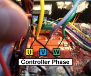
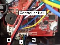
So I decided to permutate the phase wires... This is a sensored motors, so I think I also have to permutate the hall wires. So basically I made calculations and there are 36 possible combination. I will try them all and report back...

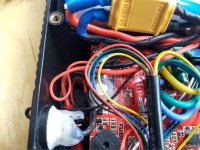
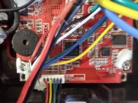
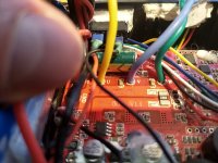
Controller Phase wires.jpgController Hall.jpgE3272493949993D61754B837AC14B3D6B690CC1414B599C6E6C6A9C4447694CDCC23A0CEE003.jpg


So I'm stuck.....
There are three combinations which seems to run equally smooth and in forward direction when I run them in free air...
Are all three combinations #7, #23, #33 as good as each other or is there only one combination that is the better one ?

Combination #7

HALL (controller to motor) is : u-Yellow v-Green w-Blue
PHASE (controller to motor) is : U-Green V-Blue W-Yellow

Combination #23

HALL (controller to motor) is : u-Green v-Blue w-Yellow
PHASE (controller to motor) is : U-Blue V-Yellow W-Green

Combination #33

HALL (controller to motor) is : u-Blue v-Yellow w-Green
PHASE (controller to motor) is : U-Yellow V-Green W-Blue

My controller came factory in reverse, so I'm trying to sort it out,

Any idea ??

Matador
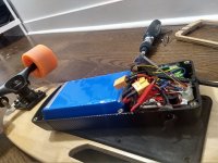
 
Assuming a neutrally-timed sensor position, there are always six valid combos, three forward and three reverse. They are identical because they are simply shifted around a circle. Draw it out in a circle and you'll see what I mean.

You'd have to test them under load to be sure timing actually is neutral and that they really work, but if one does, all three should.
 
Thanks amberwolf,

So kindoff going 1,2,3,1,2,3,1,2,3 gives the same result as 2,3,1,2,3,1,2,3,1 or 3,1,2,3,1,2,3,1,2 ?
I read some post about this a minute ago ? This is really interesting stuff.
I feel i'm really starting to better understand how ebikes work.

I think it's a neutrally timed sensor position.
Seems like in free are, all three possibilities that run smooth (3 forward, and 3 backwards) all consume the same amount current (0.90A at 29.2V) in free air.

I ended up picking combination #7, which works perfect.
Now when i turn on the Small Fish Plate electric skateboard, it starts up in the forward direction by default !

Matador
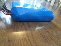
 
More photos of the board and board guts.
More specifications on the components (motor, PU sleeves, ESC mods, etc)...
Info on overvolting / overclocking the board to make it go faster...

Follow this link:

https://www.electric-skateboard.builders/t/chinese-board-repair-and-upgrade-help-so-you-bought-a-chinese-board-huh-wanna-talk-about-it/10607/6

Matador
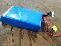
 
EDIT: Now July 30th 2020, gave it a full bulk charge, stopped at 88% charge...
B1 - 3.90V (-) B1 - 3.87V (-)
B2 - 3.99V B2 - 3.96V
B3 - 4.22V B3 - 4.20V
B4 - 4.20V ----[Dschrg]---> B4 - 4.17V -----[Manually balance each group]----->
B5 - 4.20V B5 - 4.17V
B6 - 4.22V B6 - 4.20V
B7 - 4.22V (+) Total: 28.3V B7 - 4.20V (+)

Dunno why it drifted so much.... I hadn't checked voltages in a while though (probably not since October 2019) and used it maybe 10 cycles since then... At least I know the High Voltage Cutoff (seems set at 4.22V) works, protecting from overcharging. Had it continued to the top charge of the charger (29.4 V), groups B3, B6 and B7 could have reached 4.38V !!
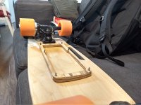
Matador.
 
Back
Top