smeagol222
100 W
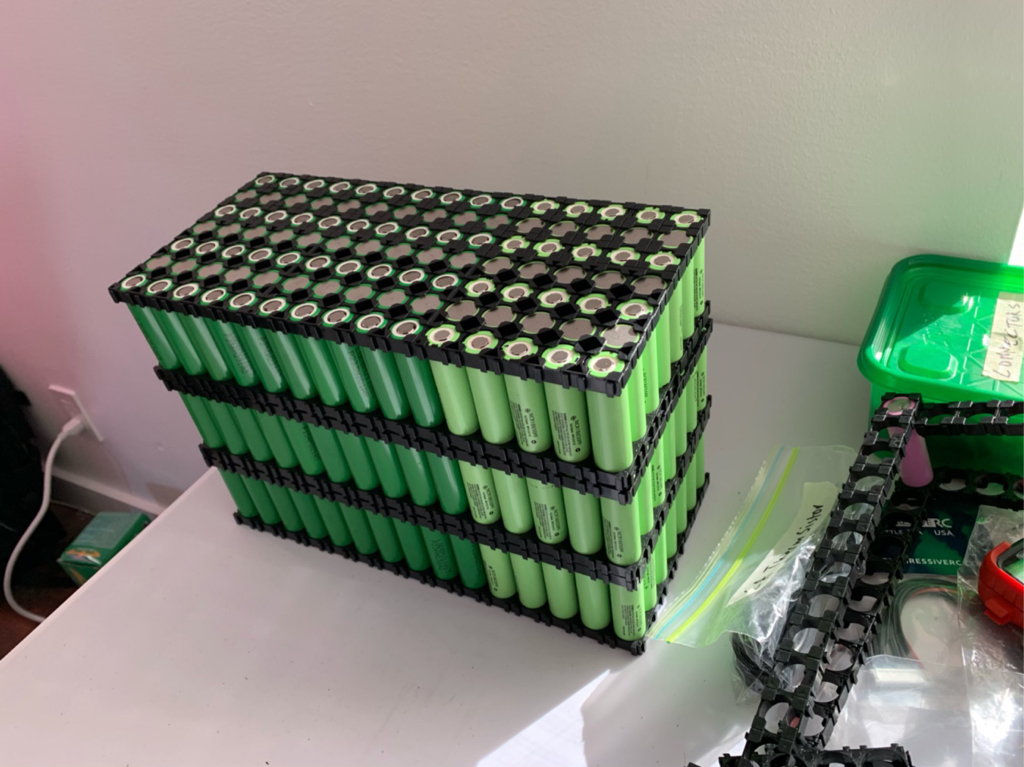
I'm building a 21s15p pack split into 3 layers (for size and balancing contraints) - no BMS
each string 10 cells LG mj1 + 5 cells PF
Its going only need to produce about 120amps peak (my build link below with kelly controller limits battery to 80%)
https://endless-sphere.com/forums/viewtopic.php?f=10&t=85164&p=1454286#p1454286
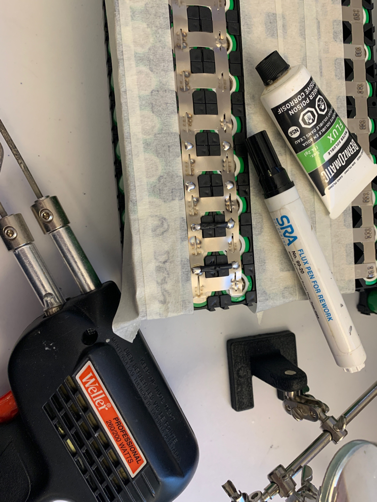
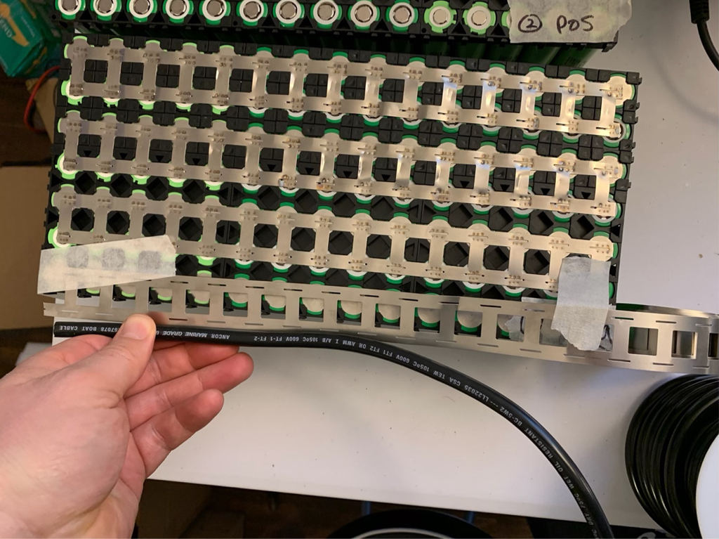
I'm have some 2p nickel band strips that I've been using, they have little slits in them (not sure why) - should I be worried about this?
I was just thinking because of the split its less nickel & worried about power. Each cell is capable of 10a discharge, but only will need to produce 8a peak.
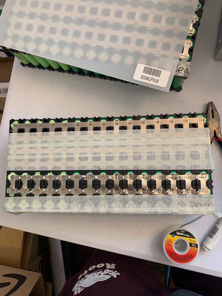
I've spot welded with 6 welds per cell, normal nickel strips that are not 2p would have more contact. Wondering if anyone has had experience with these 2p "band" types if there is any effect on performance.
Also for each of the packs the last string I was thinking of using another 2p band and then soldering an exposed 6 awg wire all the way along? Is this neccessary? Or can I just solder the 6awg to the end of the row?
If the 6 awg doesn't need to be the whole way along, I could just use single strip nickel for the last row and solder 6 awg just to the end.
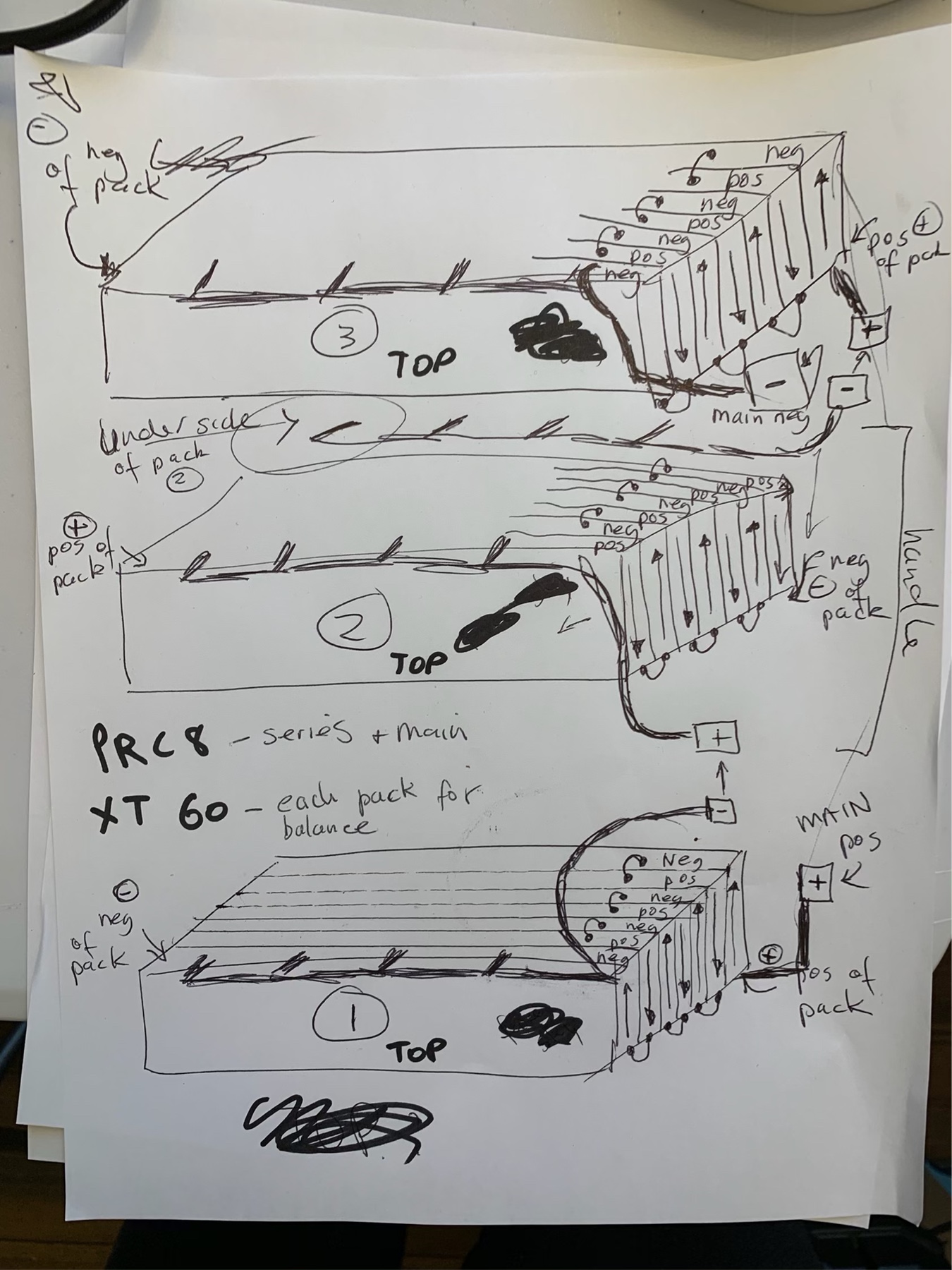
I have a very crude sketch of the design, I'm going to add plastic sheet in between the stacks.
- 6 awg + PRC8 Connectors as the main wire output for entire pack
- 6 awg + PRC8 Connectors as series connections between each 7s pack
- 12 awg + XT60 as charge for each 7s pack
- 7s balance leads per layer
Any battery building advice would be greatly appreciated
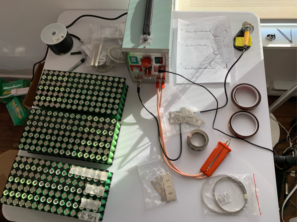
each string 10 cells LG mj1 + 5 cells PF
Its going only need to produce about 120amps peak (my build link below with kelly controller limits battery to 80%)
https://endless-sphere.com/forums/viewtopic.php?f=10&t=85164&p=1454286#p1454286
I'm have some 2p nickel band strips that I've been using, they have little slits in them (not sure why) - should I be worried about this?
I was just thinking because of the split its less nickel & worried about power. Each cell is capable of 10a discharge, but only will need to produce 8a peak.
I've spot welded with 6 welds per cell, normal nickel strips that are not 2p would have more contact. Wondering if anyone has had experience with these 2p "band" types if there is any effect on performance.
Also for each of the packs the last string I was thinking of using another 2p band and then soldering an exposed 6 awg wire all the way along? Is this neccessary? Or can I just solder the 6awg to the end of the row?
If the 6 awg doesn't need to be the whole way along, I could just use single strip nickel for the last row and solder 6 awg just to the end.
I have a very crude sketch of the design, I'm going to add plastic sheet in between the stacks.
- 6 awg + PRC8 Connectors as the main wire output for entire pack
- 6 awg + PRC8 Connectors as series connections between each 7s pack
- 12 awg + XT60 as charge for each 7s pack
- 7s balance leads per layer
Any battery building advice would be greatly appreciated
") :thumb:
:thumb: