600W BMC conversion to external controller

fechter

Administrator
Staff member
Joined
Dec 31, 2006
Messages
16,545
Location
California Bay Area, USA
From the archives: This is the motor I use on my scooter seen here:http://endless-sphere.com/forums/viewtopic.php?f=12&t=582

The 600W non-hub internally controlled motor was mostly found on earlier Currie Tech electric scooters. The motor is made by BMC in India, the same place where the BMC hub motors originated. They use the same winding and magnet configuration. Due to poor controller design, the things had a bad habit of blowing up, making the whole unit useless. It is possible, however, to separate the wires from the motor and internal controller and use the motor with an external controller.

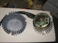
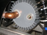
The motor typically looks like this:Name plate.jpg
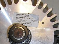
 
The finned cover is held on with 3 small screws and is easily removed.
The sprocket and motor shaft are held on by snap rings on the shaft and are removed with a snap ring pliers.
BMC 600w motor apart.jpg
 
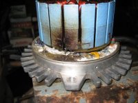
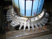
The internal controller is potted in epoxy. This makes getting the wire out sort of a chore. What seems to work is to heat the epoxy to around 100C (boiling) with a heat gun, torch, or pan of boiling water, then it softens to a 'rubbery' consistency which can be dug out with a small screwdriver. As it cools off, it gets hard again, so several heating cycles may be needed to clear the epoxy from around the wires. Be careful to not overheat it, as you could melt the hall sensor wires or damage the hall sensors. I found it worked well to heat the face of the motor and let the heat transfer through to the epoxy.

There are 3 pairs of wires that go from the stator to the potted controller. The idea is to dig out around where the wires attach to the board and desolder or cut them off with as much length as possible. You also need to keep track of the pairing. They are color coded on most motors.
BMC epoxy potting.jpg


The hall sensors are connected by a 5 conductor ribbon cable. This needs to be spliced too. The insulation on the hall wires will melt easily, so be careful when heating. You want to free up as much length as possible to make splicing easier.
BMC hall wires.jpg

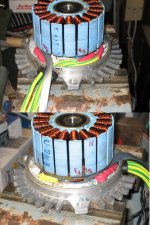
Next, I soldered on extensions for the phase and hall wires and heat shrinked over the connections.
BMC new wires.jpg
 
Once that's done, you can re-assemble the motor.
View attachment 1

On mine, I also drilled a pair of 7/8" holes in the cover and epoxied in some plastic fittings so I could run forced-air cooling. The forced-air allows nearly double the continuous power level without overheating.
Forced air cooling.jpg
 
For a controller, I'm using an analog Crystalyte. There may be compatibility issues with some brushless controllers, so you really need to test carefully when first trying a controller.

I also don't seem to have a record of which hall wire goes where. As I recall, the black and white wires coming from the motor halls correspond to the black and red wires on the Crystalyte halls. Beyond that, I can't remember. As a result, it may be necessary to go through the combinations to find the right one.
See: http://endless-sphere.com/forums/viewtopic.php?f=16&t=3484
When you get the right one, the motor should start from any position and not draw more than around 4 amps at 48v with no load.
 
Back
Top