Hall Sensors'b'Gone

incememed said:
Extrapolated for the HS3548:
kv: 9.1
R: 103-142 mohm
L: 225-293 uH

Thank you---I did a lot of searches on the forum and via google but didn't find that other forum's thread.

I'll try it out with the different kV, the resistance and inductance are close to what I have it at right now (100mohm and 240uH).


Phase current limit is in there, what is removed is battery current limit.

You're right, of course; I was just confused (probably because of the label for the display-only field above it, "expected max battery current", and the tiny print I end up with if I zoom out far enough to see everything on my screen at once). :oops:

I'll play with that, too, once I have the motor running right with the right settings.


FWIW, the test ride was ok; as long as I kept throttle down while speed was low, it was ok, but I pretty much always had to start up using the other motor with the generic controller, then after a few MPH cease throttle on the generic, and begin throttling up the SFOC5 / HS3548, rapidly being able to increase throttle as I approached 20MPH. If I felt "roughness" (felt like a ribbed road surface thru the pedals; much less rough than the stutter is) I'd just back off throttle and it would be smoother, then I could continue throttling up. About 19MPH I could reliably hit full throttle, but only for an instant cuz I'd already be at 20MPH then and have to back way off.
 
I tried a number of variations on those new values from the extremes to the averages, and none of htem work as well as what I already had. I think the 9.1kV may be wrong, because if I use the 12.48kV it works much better. The actual kV may be something higher or lower than that, I will have to do an RPM test to see if I can find out what it actually is.

For today's long test, about 11 miles, I'm using 12.48kV and 100mohms and 200uH, after a bunch of incremental downward value adjustments on short neighborhood rides first. With these values, I can use full throttle from almost zero, if I start by either pedalling a bit or using the other motor, to the point the SFOC can begin powering the wheel and make forward movement. (around a couple MPH).

Because the HS3548 is a much lower-torque motor than the 4503, the system has MUCH lower acceleration rates, especially at the bottom to middle of the 0-20MPH speed range.

I'm sure increasing the phase current above 140 would help that, but until I am more sure of the motor settings I don't want to try that.

The HS3548 gets pretty hot (to my hand; there's no temperature sensor built into it and I haven't moved over the SFOC-supplied one from the 4503 yet), compared to using it with the Grinfineon "generic" controller. I'd guess it's 20-40F hotter, but my hand isn't exactly calibrated. ;) I don't know what temperature it was at with Grinfineon, or now, but it's hot enough now I couldn't keep my hand on it for more than maybe 10 seconds at most. Could keep it there all day with the Grinfineon, even at the hardest I run it at, stop and go traffic, and it'd be uncomfortably warm at worst, but that's all.

I don't know how much of that is caused by the uncertain motor settings, but it shouldn't get that hot, since ATM I'm basically using it in conjunction with the left side 4504/generic combo, just like i have to with the Grinfineon, for accleration from anything that matters for quickness (wherever cars are behind me, which is most places), and using it on it's own (just like with the Grinfineon) for cruising at 20MPH or less (which takes around 900w).

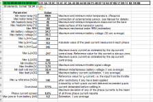
I haven't checked the SFOC temperature by hand, since it's out of reach under the center of the trike bed now, instead of near the side. According to the stats from the end of yesterday's long test ride (see below) it was 65C at the max on that ride (and 45C min).


12 34 00 00 00 C5 3E 85 54 28 01 6A 18 8C 19 4C 4C 2A 45 B0 44 68 D4 F3 4B 5F 12 04 5F BD 17 8B 11 B2 1B BB
stats 090618 1.png


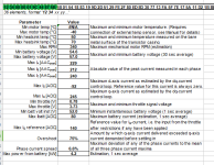
Today's long test ride was in hotter air temps by a few degrees, no clouds at all (unlike yesterday that had a few here and there), with almost no breezes so pavement was hotter, so everything closer to the pavement is also hotter (including the SFOC under the trike). So the SFOC got up to 70C this ride, starting out at 50C at the beginning of the last leg, presumably, with a couple hours between stopping at that point and continuing home.

12 34 00 00 01 9C 44 E7 5B 5B 01 54 18 83 19 9D 2D 51 29 FE 2F 80 ED B3 30 77 13 FA 5F 7E 17 5A 11 D2 1B BB
stats 090618 2.png


I know there is a new setting to "force" the SFOC to output more current at lower speeds, by setting it to output what it would have at a specific higher RPM. The default says it's set to 40RPM, which would be somewhere around 3-ish MPH for my wheel size, I think. I haven't tried changing it from that yet (again, wanna make sure I have the motor setup right first).

I'm assuming this is similar in effect to the "block time" settings in the generic controllers, though it works in a different way.

It's there to fix the issue that the SFOC doesn't pull as hard (accelerate as quickly) at low speeds as generic trapezoidal (and possible sine, but dont' have one to compare) controllers. In my case, anyway, it doesn't really get great acceleration going until it's in the top quarter of my total speed range (0-20MPH), and really only in the top half or less of the top quarter.

I know that many generics have a "block time" in them where they just dump all the current they can handle into the phases, ignoring any limits, and doing enough stop/start accelerations in a row can blow them up (done that), so I don't want to do that to the SFOC. ;) But I'd like to find out why it doesn't accelerate as quickly, all else the same, as the generic trap controllers on the same motor, and fix that. Probably this new setting will help, once I get far enough to test it safely.

I'm sure I need to work out the correct motor parameters first, and that might help, but AFAIK I had the right ones on the 4503 and that seemed to have the same essential problem.

I *think* it's a little less noticeable on the 4503 because it's got more torque to be had by a higher current controller like the SFOC, compared to the "40A" Grinfineon, which at it's best couldn't match what the SFOC could get out of the 4503...but the HS3548 doesnt' have as much extra that the SFOC can make it do vs the Grinfineon, so it's more noticeable on hte HS3548 that SFOC can't push as hard as the Grinfineon at the lower speeds.

ANyway, I'm rambling now, I think I need a nap. :/
 
Oh, and Marcexec helped me find another reference for the HS3548, with part of the info needed
https://endless-sphere.com/forums/viewtopic.php?f=30&t=69970&p=1409533#p1409533
showing 84mohm 13kV (no inductance though)

This is closer to what I tested (with better results than other numbers so far) today, which was 100mohm and 12.48kV (and 200uH inductance).

So I'll try those, and see what happens from there.

But not right now...I still need that nap.
 
Thank you---I did a lot of searches on the forum and via google but didn't find that other forum's thread.
http://forum.index.hu/Article/showA...035728&token=6a0196735cfd18116d2b604e50e97060

It appears that ebikes.ca uses something close to 9.2 in their simulator for the HS3548.
https://www.ebikes.ca/tools/simulator.html?bopen=false&motor=M3548

But then again, I have had a C80100-180 labelled and sold to me as the 130 kv variant. (Before I figured it out, controller and motor got very hot from regular riding, as in >>100 C).

I know there is a new setting to "force" the SFOC to output more current at lower speeds,
Current is always and only modulated by the throttle, no middlemen. The user is in control of the current at all times, except for when limited for thermal reasons.

The startup algorithm is work-in-progress to get cleaner un-assisted startups from standstill at low to moderate load. While it works well with my geared RC-setup, I have not heard any other user having any help from it, yet. In its present form I doubt your setup has much to gain from experimenting with this function.

As for now, I refrain from implementing any automated/forced/sequential startup routines, since that would perhaps work well under some circumstances but likely get in the way under others, such as when stuck in mud, rocks, steep inclines, etc on the trail. And it would be vehicle dependent, so less universality.

I know that many generics have a "block time" in them where they just dump all the current they can handle into the phases, ignoring any limits, and doing enough stop/start accelerations in a row can blow them up (done that), so I don't want to do that to the SFOC. ;)
The main goal when developing the SFOC was to make it thermally indestructible. It is supposed to limit itself to what the hardware can sustain. So by all means, give it hell. I see this prototyping as an anti-fragile process, if a design or manufacturing flaw can be tied to a failure, it can be improved on. I will try to get you a replacement if that would happen.

Speaking of replacements, there is now an 84 V variant available for anyone who wants to dive in. Bike, go-kart, plane.

But I'd like to find out why it doesn't accelerate as quickly, all else the same, as the generic trap controllers on the same motor, and fix that.
I've had others report the same, motor "comes alive" as rpm increases. Rotor position estimation plays a role here, and I'm working on that. Once the cut-outs and the hiss and the high temp are resolved, we can get to some more explorative testing.

That being said, upping the phase amp limit does make things happen.

In comparison, the generic controller translates throttle position to semiconductor duty cycle. At low speeds, there is not much bemf to stop the resulting flow of current, and with high power setups off you go whether you like it or not.
 
incememed said:
It appears that ebikes.ca uses something close to 9.2 in their simulator for the HS3548.
Seems so strange to find so many values for one motor out there. I wonder how much of it is simple data entry mistakes, and how much of it someone having been sent the wrong motor vs what it's marked or what they ordered (like what happened to you), so they report back numbers for a different motor without knowing it. (could even be the case for my own motor) And how much people reporting data that they tested incorrectly.

Anyway, I did a short round the block of testing with the 84mohm and 13kV, leaving inductance at 200uH, and it ran about the same as it did with the 100mohm and 12.48kV. The "washboard" vibration was more pronounced, however, when pushing throttle higher, at any speed, not just low speeds. The controller and the motor both got pretty hot, checked by hand. Stats were going to be at the end of the post, but will be attached later; I have puppies nosing around and it's getting hard to type. Gonna have to go do playtime first.

THen I changed the inductance, up to 250uH, and was about to try again, when I remembered (because of the stats showing negative for minimum motor temperature) that I hadn't enabled the temperature sensor in the separate page for that on the settings sheet. So I "x"d the box for that, leaving the rest of the settings as they were (because I'm using the supplied thermistor, transferred over from the 4503 to the HS3548).

I then hooked up to resend the settings, but realized that the controller doesn't get this info, it already just reads whatever is attached. The temperature sensor stuff is just for the stats sheet, so it can interpret the numbers the controller itself sends back, for any particular sensor.

So I disconnected the serial cable, and switched the controller on at the Status LED panel, then tried an onground test without me on the trike, to see if it could push it forward on it's own, and it "stuttered" instead, but louder than usual (not as loud as the BANGs, but something a lot like the stutter I get when the generic trap sensorless controller gets "stuck" trying to startup the other wheel). I let go throttle immediately.

I saw a flashing code but wasn't looking directly at the LEDs, and by the time I was, it had gone blank. I then lifted the side of the trike off ground, to try a no-load wheel test, but got no throttle response. I switched it off and on at the status, but no startup-sequence on the LEDs. Power cycled at the battery cutoff, and same--no response. Rest of trike is operating normally, including leftside generic controller, and they're all powered from teh same BMSless battery, etc.

I felt the controller and motor and they were hot, not too hot to keep my hand on but much warmer than the 100F+ degree air. At a guess, possibly 120-130F. Don't presently have access to the IR thermometer.

I disconnected power again (at the batteyr cutoff), and tried to get stats, but there was no responce (or status LED).

So I'm letting it all sit unpowered for a long while during dinner/etc, and see if it "recovers", in case it was overheated and at shutdown temperature. I may have a nap first, too.


Current is always and only modulated by the throttle, no middlemen. The user is in control of the current at all times, except for when limited for thermal reasons.

The startup algorithm is work-in-progress to get cleaner un-assisted startups from standstill at low to moderate load. While it works well with my geared RC-setup, I have not heard any other user having any help from it, yet. In its present form I doubt your setup has much to gain from experimenting with this function.

Ah; ok. I misunderstood it's mechanism. I'll still try it once I get that far; whatever results I get may help you anyway.


As for now, I refrain from implementing any automated/forced/sequential startup routines, since that would perhaps work well under some circumstances but likely get in the way under others, such as when stuck in mud, rocks, steep inclines, etc on the trail. And it would be vehicle dependent, so less universality.
True. Unless there's some way to select "which routine" a particular system uses, and just include a few potentially useful ones, but that would probably make things unnecessarily complex. :/


The main goal when developing the SFOC was to make it thermally indestructible. It is supposed to limit itself to what the hardware can sustain. So by all means, give it hell. I see this prototyping as an anti-fragile process, if a design or manufacturing flaw can be tied to a failure, it can be improved on. I will try to get you a replacement if that would happen.
I'm not actually worried about blowing the controller (although that may have actually happened earlier tonight; we'll know later), I'm worried about breaking more axles. ;) I have a few controllers I can use, though they are just generic 12FETs of various types, 20-40A battery current limits. Motors are another thing....

(depending on how it breaks, I might have to do some creative roadside repair just to keep the wheel on there to let me get home--been lucky to not have to do that so far)

That BANG! problem happened at higher currents, and I'm not eager to experience one on the HS3548's axle, at least not until I have "bulletproofed" the 4503's axle and gotten it ready to go back on the trike.

I do still have an old X5304 (smaller cousing to the X540x series), taht I've repaired an axle on, but it's an untested repair, and it's not laced in a rim, so to even test it I'd have to take the spokes and rim off something else and lace it up. Past that, I'm out of motors that are capable of enough torque to be useful on the trike. (I still have a rear "2807" type, but it's unlaced, and not a high torque motor by any means...everything else is a front motor IIRC, and would require rebuilding the trike's rear wheel mounts to use. (the X5304 is actually a front motor, but the axle repair allowed me to lengthen the inboard side to let it work in place of a rear, hopefully).

If I had a better way to replace axles with bigger better designs, and make new covers with big bearings, I'd just do that, and not worry about breaking stuff, but I don't have that ability yet, and I have to use the trike for everyday stuff.


I've had others report the same, motor "comes alive" as rpm increases. Rotor position estimation plays a role here, and I'm working on that. Once the cut-outs and the hiss and the high temp are resolved, we can get to some more explorative testing.
That sounds like a plan. :)

Cuz one thing people generally expect from a high power controller is being able to access that power at any speed, and get potentially wheelie-popping tire-smoking torque :) if their vehcile/weight/motor etc would otherwise allow that to happen.

(I suspect that if I could get full current at zero speed from the SFOC5, and I had one on each of htose MXUS 450x''s, I could probably at least lift the front end off the ground a little bit. Maybe not with me on it...but that's ok; I'm not after wheelies or smoking tires. I just want the fastest possible accelration given the torque potential available, from zero speed up to 20MPH, and mostly down at the bottom end of that speed range.

Having the really good accleration even at 20MPH (much better than the generics) is potentially useful in traffic situations, where a car or truck / etc suddenly decides to be where I am, and traffic behind me would run me over if I braked to avoid colllision, but there's almost always clear space in front of me because I'm slower than most other traffic on roads where this is potentially going to happen.

But beign able to get out of the way of traffic behind me at a red light turning green is also important, as well as several places I frequently have to make turns at where I cross a road indirectly--turning right at an intersection, crossing two to four lanes in a few dozen yards, and making a left turn from the isolated median-turn-lane. These are places wehre it's not possible to go straight thru the intersection, either illegal or physically impossible due to intersection construction.

The catch is that while I can turn right even during a red light for my direction, I can only do it when there's a big enough traffic gap to ensure I can accelerate into it *and* reach the safety of the median lane. The quicker I can accelerate, the more likely I can do this safely, especially if I have "reserve acceleration" at max speed in case some driver sees me and accelerates to try to prevent me from crossing (it happens to cars too); and if I"m already committed I *have* to get over and out of the way, or risk being hit from behind by a car that simply doesn't care or doesn't realize how much slower I am than they are, etc.

Right now I may have to wait for up to a couple of minutes (the whole light cycle time at the slowest-changing one), and since cars are waiting behind me that *could* have turned if I weren't in their way, they sometimes get impatient, and every so often someone will be angry and either yell at me to move (which I can't) or do something unsafe and just go around me in the next lane to the left, or between me and the next lane, while traffic is still zooming past in front of us. This kind of thing is still going to happen regardless of capabilities...but the more I can prevent it, the safer everyone (especially me) is. ;)

The other separate issue is hauling cargo especially really heavy stuff in the trailer, because taht can more than doulbe the mass the motors ahve to move, and the faster I can accelerate from a stop with all that, the better, too. (which equates to being able to haul it up slopes, which are not very long here in PHoenix for the most part--I don't need to go where there's hills or mountains, very much).

It's also more fun to be able to accelerate really really quickly. :lol:


That being said, upping the phase amp limit does make things happen.

In comparison, the generic controller translates throttle position to semiconductor duty cycle. At low speeds, there is not much bemf to stop the resulting flow of current, and with high power setups off you go whether you like it or not.
Not too worried about that with mine, given the inertia it has to overcome. :)

I'm sure it will get better both as the software evolves, and as I get settings nailed down to be able to increase the current limits.
 
(I suspect that if I could get full current at zero speed from the SFOC5, and I had one on each of htose MXUS 450x''s, I could probably at least lift the front end off the ground a little bit.
That is where the bar is at.

I get the impression connecting the external temps sensor causes increased current through the MCU die, causing it to overheat and eventually lock up.

Last time a sensor was connected:

amberwolf said:
But after a short set of test runs up and down the street, not even 3/4 of a mile, when I pulled into the yard to stop and get the stats, the controller acted strange. First I powered it off, shutting down the trike, then I setup realterm to receive the stats, and plugged in the serial cable. NO response at all, not even the usual power-on Status LED sequence, etc. So I disconnected and reconnected, and nothing. I shut down everything on the computer, and rebooted it, and unplugged/plugged the USB-serial in case it might be that, with no change. Even powered on the trike with serial not connected to see if it would oeprate, but no go.

After messing around with stuff for a few minutes, I rolled the trike on it's side so I could check for disconnections or whatever underneath, and found the controller so hot I couldn't keep the palm of my hand on it very long (almost 10 seconds), and couldn't put the back of my hand against it at all. The motor was very warm but not yet hot, but it was getting hotter. I didn't have access to the infrared thermometer today, or I"d give the readouts.

I was hot myself, and tired, and kinda frustrated with the day so far, almost all of it spent out in the heat (even though in the shade, still near or at 100F since late morning-ish). Since I wanted to go in and type all this stuff up, and eat something, but I also wanted to get the ride stats to put in here, and didn't have the patience to wait for everything to cool down on it's own. That could take quite a while. So I got some ice out of the deepfreeze and used that to cool the controller and motor casings down to where I could keep touching them.

Once I did this, which took about 10 minutes (about 11 minutes longer than I wanted it to), I could now get stats, but they are all zeros again. :/

I would suggest connecting the sensor (any thermistor) directly to the SFOC5 motor temps sensor cable, and just measure ambient temperature for a couple of runs, and go from there. For now, I would not connect anything until the new motor is running as expected.
 
incememed said:
I get the impression connecting the external temps sensor causes increased current through the MCU die, causing it to overheat and eventually lock up.

I'm not sure. Unfortunately, I can't test any further yet, because something has failed inside the SFOC5. :( Apologies for the troubleshooting ramble below, but I wanted to give you all the details I have, in case they're helpful. If there is anythign I didn't give that you need, tell me and I'll try. :)

(You know more about engineering than I do, but how is the sensor circuit wired up that would allow current flow thru the MCU? If it's a type of direct connection, that's a potential failure point from system shorts, which are a very common thing when people spin out hubmotor axles, which is also a common enough thing on high powered builds that aren't secured properly. Such direct connections of MCUs with hall sensors in motors is something that kills sensored basic controllers in such situations, when they get shorted to active phase wires. Can't protect against everything, but.... :) )


I began by disconnecting everything from it, except the Status LED panel with switch, and battery power. Even with this, I got no response from it. Disconnected even the Status LED panel, and tried reading it from the USB serial, and no response there, either.

Investigation with a voltmeter finds no 5V on any of the cable port pins that should have it per the manual. Sometimes it has around 2.5v there, sometimes it has less than a volt, down to 0.03v (with the Status LED panel connected, and switched on).


I removed the SFOC5 from the trike entirely, and began testing all of the wiring that hooks up to it, that's on the trike. I found no problems, *except* the 5V line to the thermistor inside the motor was a dead short to the trike frame. Since nothing else (including battery ground) connects to the trike frame, there's no reason that should make any sort of difference. I verified none of the phases have less than a few megohms to the frame, or any other wire from the motor, battery, throttle, etc.

The SFOC5 itself is attached to the wooden cargo deck, not the metal trike frame, so it's casing couldn't be shorted to anything (even if there was any conductive path from it's casing to something internal).


I opened up the HS3548 motor, and found that I'd tightened the ziptie down too far on the wires from the thermistor, securing them to the motor's internal frame to keep them away from the rotor. As soon as I loosened that ziptie the short went away. I can't see any damage to the insulation but it's obviously there. So I reinsulated them and secured them in a different way that cant' do that. Reassembled and remounted the motor, and retested again, no short, everything proper resitance to each other and high resistance to frame.


So while I don't know what else could've been shorted to frame along with the 5V, nothing should be now, either.

I didn't retest the SFOC on the trike at this point, but rather brought it inside and began testing it using a spare battery and it's STatus LED panel and a voltmeter.

At the STatus LED panel switch, it has 12v on the center pin when it is off. When it is on, that drops as far as 3v, with 0v on the other pins.

If you can tell me what voltages I should be able to measure at what points, I can test the internal low-voltage-power supplies. Or if it has any internal fuses, I can check those, too.

Or if it's possible to use an external 5v supply to test the rest of the SFOC (with it's own supply disconnected internally if necessary), I have a number of ways of supplying that, including lab PSUs, or USB power supplies/chargers, etc.

BTW, if there *was* somehow a short from say, the thermistor's 5V line to system ground, and that damaged the 5V supply inside the SFOC5, it might be prevented with either a protection circuit on the 5V line, or by changing to use ground as the external reference connection for the thermistor rather than 5V. (which would also make it compatible with the default factory wiring for various hubmotors that come with thermal sensors built in that use a common ground for hall and thermal sensors).


I would suggest connecting the sensor (any thermistor) directly to the SFOC5 motor temps sensor cable, and just measure ambient temperature for a couple of runs, and go from there. For now, I would not connect anything until the new motor is running as expected.

If I can fix the low voltage power supply issue (if that's what's wrong), then that's a great idea I should've tried first. :/

I'm not sure that the temperature sensor being connected made any difference in the situation you'd quoted; I think it was just the settings I was using and the way I was pushing it, vs teh way the firmware worked at the time, vs the high air temperatures, and I just pushed it hard enough to overheat things. I can't really know, though. :oops:

The heat in this new case is also more likely caused by still-wrong settings for the different motor and high air temperatures, though I wasnt' really pushing it like before.
 
Shorted MCU. I'll send you the return address by PM.

Hopefully you are not discouraged and we can continue the testing as soon as it is repaired. We have yet to lift that front wheel!

Thanks to the impeccable reporting from all the testing, we can get some insight as to what might be going on.

In the MXUS, something happened (or was amplified) when the MXUS KTY83/110 sensor - which was showing reasonable values both in your offground and ride tests - was replaced by the provided one. I wonder if it may have been an insulation problem with the sensor, sensor wiring, or with the MXUS itself. It would be interesting to measure MXUS phase to core insulation. In any case, the MCU had a near death experience.

With the new motor, because of your diligent post fault probing, this time we can get closer to the root cause. Now we know the entire trike frame acted as an antenna to the MCU VDD input, picking up six different phases being switched, and potentially picking up battery potential if any of the phases have irregularities in the insulation. Still, such voltage may not instantly kill the MCU, since it is galvanically separated from the battery NEG, but apparently, it decided it was time to throw in the towel.

Edit: 5 V bus is obviously a weak point, better protection is now on the To Do
 
incememed said:
Shorted MCU. I'll send you the return address by PM.
I got the PM; I'll get it sent out as soon as possible; I work hours that won't allow me to make it to the post office in time until Thursday, unless things change.

Before I send it off, if it is ok with you, I'd like to open the case and take a few pics, because I'm still very curious how it's built inside. :)

Hopefully you are not discouraged and we can continue the testing as soon as it is repaired. We have yet to lift that front wheel!

Not discouraged, just saddened that I now have to listen to my noisy trap controllers for a while. I really like the silence of the FOC, and I'll also miss the easier throttle control (though I can simulate that with teh CA's current throttle, it's not as instantly responsive, etc). Experimenting is fun, too. :)

Not sure we'll be able to lift teh front wheel with just one SFOC, though it's worth a try anyway. ;)


In the MXUS, something happened (or was amplified) when the MXUS KTY83/110 sensor - which was showing reasonable values both in your offground and ride tests - was replaced by the provided one. I wonder if it may have been an insulation problem with the sensor, sensor wiring, or with the MXUS itself. It would be interesting to measure MXUS phase to core insulation. In any case, the MCU had a near death experience.

I'll measure the motor windings to axle (which includes laminations/core), but I already removed the old wiring in preparation for welding the new axle end on. I don't remember where I put the old wires in the pre-puppy-arrival stuff-shuffling, so can't test them unless I run across them.

The SFOC-provided sensor itself and it's short included wires in the MXUS (and now in the HS3548) was insulated away from the windings and laminations and the motor's internal framework by a layer of electrical tape (don't have any Kapton). So the actual sensor shouldn't be able to short against anything, even if it's own insulation was damaged. The way the wiring inside was run shouldn't have allowed a short either, but without being able to test it, can't know for sure.

The MXUS-included sensor is glued in place in the windings. I can still measure that to laminations/etc.


With the new motor, because of your diligent post fault probing, this time we can get closer to the root cause. Now we know the entire trike frame acted as an antenna to the MCU VDD input, picking up six different phases being switched, and potentially picking up battery potential if any of the phases have irregularities in the insulation. Still, such voltage may not instantly kill the MCU, since it is galvanically separated from the battery NEG, but apparently, it decided it was time to throw in the towel.
That actually makes a lot of sense; I've seen the RF from brushed motors kill FETs on brushed controllers, and stray signal sources cause all sorts of havoc inside various analog electronics (especially back in my ham radio days). I can imagine the MCU would be even more sensitive to such damage.

Perhaps a small design change is in order to prevent that possibility? Maybe if there isn't one already, an instrumentation op-amp frontend for the MCU pin, just to isolate the signal from the sensor itself, and moving the reference from 5v to ground, so there's no noise input possibilyt into the MCU's power supply. Again, I defer to your engineering knowledge, as mine is minimal (mostly from the technician end of fixing things).
 
That sounds like a proper way to interface the signals, including the throttle. And the 5.1 if there ever is one will for sure reference the sensor to GND.

I will have to ask you to contain that curiosity for a few weeks, need to receive the controller exactly the way it was during operation.
 
Ok, got to the PO so it's on it's way back now.

In the meantime, I'm considering a serious change to how my hubmotors mount to the trike, partly just so I never have to deal with axles broken by torque again. Not sure I can pull it off, but here's a thread with the idea:

https://endless-sphere.com/forums/viewtopic.php?f=30&t=96354
 
Although the damage to the control chip was minor (memory, etc intact), I did end up replacing all 5 V silicon components, and some caps, just to be sure. Transient suppressing diodes are now each temp sensor wire. I have also made some hardware updates reflecting improvements made in the last few months. Let me know if you have any other concern before shipping.

Footage from pre-shipment testing of this controller with 84 V battery.
[youtube]kTRVoZOKTas[/youtube]
 
I can't think of anything at the moment, but I'm wiped out tired. Lemme sleep on it and see if I can think of anything by tomorrow night.

The improvements/repairs sound good.

I forget: is the thermal sensor still 5v and signal, or is it ground and signal now? (I have the sensor in the leftside MXUS (4T? man I'm tired, got CRAFT syndrome) wired completely independently of the rest of the motor just in case; IIRC it's a regular 10k thermistor....).


I've still got to finish repairing and upgrading the axle on the rightside MXUS, and remake the trike frame/dropouts to match it, so testing can continue with that one.

And I have to do some axle/dropout upgrading on the leftside one before I'd test with any serious current on it, so I don't end up with the same broken axle problem as the rightside. ;)

I put in for the last week of October off, but haven't yet seen it approved. If I get it, it'll give me the time to do the work, otherwise the really high current testing will be delayed a bit until I can do that stuff (so I don't end up losing a wheel going down the road should something like the previous issue crop up again).
 
We are stuck with +5 V referencing for the thermistor for this batch of prototypes. It's on the list.
It now accepts all thermistors, configurable in the S&S. Data for common thermistors is provided.
 
I've been trying to think of anything else, but I haven't so far, other than below:


Since it does get rather warm in use, I was considering bolting a big heatsink I've got laying around, to the controller. Presently its' about a square foot, with fins over an inch (maybe two) high.

Can be cut down if necessary (I have several) but I was considering bolting all the controllers to it; and a DC-DC (for lighting, instead of the 4s battery) if I ever run across one. I know there's a "recess" on the SFOC casing a heatsink surface would need to fit down into, but I can cut grooves into the heatsink's mounting surface to accomodate the SFOC's casing ridges around the flat surface area.

It looks like I'd have to take the existing top bolts off to put the heatsink on. Are they threaded into the heatsink, or do they have nuts inside? If nuts, are those retained by anything, and/or do they have washers I'd have to be sure are not left floating around?

Also, do the bolts have any extra length, or are they just long enough for their present purpose (meaning, would I need to use longer bolts sufficient to pass thu the heatsink as well--I think it's more than 1/4" thick between the fins)?
 
The bolts are retained by nuts, no washer. The recess measurements are on p. 29 of the manual. The is little margin in terms of bolt length, so longer ones will be needed.

Back when the SFOC was a 12 FET, I ran an external heatsink. Now the motor overheats way before the heatsink, so not needed in my case. But my motor is small and has limited thermal capacity.

Looking forward to continued testing, will ship as soon as possible.
 
I may not "need" the heatsink either, but things that stay cooler last longer. :)

Testing will resume without heatsink first, and see where things go from there.


I'd still like to make a dashboard app or something to display the realtime data stream, but so far I haven't begun to comprehend all the stuff needed to get started. :/

I'm much better at helping others fix things up or build them than I am doing it from scratch myself, especially when it comes to programming, especially since the only way I can figure how to get the serial data into whatever device the app runs on is to convert it to BT first, then read BT port on the device.

The only way around that is if I use a laptop, which has a serial port, and the smallest one of those I have is still pretty large to put on the tiller or suspend upside down from the canopy. But it's probably how I'll need to do it.
 
Let me know if changes to the data stream would make interfacing easier.

One user mentioned the need for a "legalizer switch" - i.e. speed and/or torque limitation - which would be a possibility if two-way communication was used. You did mention reversing earlier, could also be communicated this way. Something to ponder once basic controller operation is firmly in place.
 
incememed said:
Let me know if changes to the data stream would make interfacing easier
Maybe, but mostly it's just me not yet comprehending programming what's needed. I can see the basic block idea of it...just not yet how to implement it. The first thing to be done is to be able to make a program that reads the file generated by the terminal saving the serial data stream, and displays it as human-readable data onscreen. Everything else is just getting data into that.

Have had a lot of life "getting in the way" of that (the new puppies, work, etc), so it's really slow going compared to what I thought I'd get done. (and apparently I learn a lot slower these days)


One user mentioned the need for a "legalizer switch" - i.e. speed and/or torque limitation - which would be a possibility if two-way communication was used. You did mention reversing earlier, could also be communicated this way. Something to ponder once basic controller operation is firmly in place.
If the display is the only way to do it, then I'll take it, but reversing would be much easier / better as a simple switch input, if there's any discrete inputs available. Typically reversing is just a momentary thing, easiest to control via a simple momentary switch on the bars near the throttle.

If it's part of a central display, it'd have to be turned on with the hand coming off the bars, then back to the bars for throttle, then back to turn it off; if backing up with the trailer (or some other complex reversing maneuver) it'd get tedious.

Using just a button next to the throttle (like I have now), I just hold the button whenever I'm backing up, and let it go when going forward, etc., using whichever throttle (left or right or both) is needed to help push in the right direction.
 
Someone asked the other day for how long it would run at high current before thermal limiting is activated, so I decided to test it.
[youtube]Nkmkypzdrck[/youtube]
 
Some wierd news, that might be bad, for the motor I've been slowly repairing to get it back on the trike to continue testing:

https://endless-sphere.com/forums/viewtopic.php?f=2&t=67833&p=1449433#p1449433

Short story long, the "blue" phase is shorted to the stator/axle, somewhere other than the phase wire itself (in the windings?).

Assuming nothing else in the trike's system is connected to (shorted to) the trike frame, will the SFOC5 still successfully and safely operate the motor?

I'm still working on isolating the short to fix it, but there's always the chance I won't be able to...and I'd really like to keep using the motor.

If I can't, I'll continue trying to make it work with the 4504 instead, or the old Crystalyte X5304, or the relatively hefty motor off an old Stromer I have....
 
With a galvanic short, functionality will be clearly affected. I know it too well from overheating C80100s to the point where sheath melts away and shorts the phase wire to the motor cable exit. I would not recommend operation with anything but a healthy phase.

When shorted to the motor - and consequently the frame - stray capacitances between frame and controller and frame and battery leads become substantial, which are charged and discharged every period. This gives a potential electromagnetic interference problem, and also phase current asymmetry, which affects position estimation.
 
That's what I figured. :/

I did, however, find and fix that particular problem, at least for now. Using a really stiff brush with long bristles, I "dusted" under and around all the areas windings go down thru the stator slots, where I found a fair bit of metallic dust, probably from all my axle fixing work (despite what I thought extreme multilayer precautions to keep it from getting in the motor at all).

Then I used a plastic handle to gently touch various spots while running the isolation tester at 100v range, and located an area (directly under the original position for the WYE point connection) that when prodded would change the readings. I slid bits of zipties (all I had that would fit in there, that had rounded edges/etc) under the windings, between teh stator slots, to try to push the windings up away from the stator.
file.php


Eventually I reached the point that must've caused the problem, because the readings went to the max for the range (>110Megohm). I switched ranges to 250v, and got hte max for that (>5.5Gigohm), even when tapping the area. I kept retesting as i tied things down, step by step, and got no fluctuations in reading.
file.php


So I think I have fixed this particular problem sufficiently to use the controller. I hope.


HOwever, I'm having significant troulbes getting anything other than itty bitty 14g or smaller phase wires thru the axle/bearing spaces, without damaging their insulation one way or another, and causing a phase/axle short.

I guess I'll have to use at least a few inches of really thin phase wires, for that section, and just have thicker stuff once outside the motor. :/
 
Separate question (that I haven't done much poking around for yet :oops: so there may even be a thread for this, probably posts on the internet in general):

Do you know a way I might guesstimate or measure, using the basic instrumentation I have around here (common multimeters, best of which is a Fluke 77-IIIa, little low-range Hitachi(?) portable oscilloscope, lab PSUs, etc) what the inductance and resistance of a motor is?

I could use other motors, that have no such data available for them, if I can measure their characteristics well enough for the SFOC's needs.

It's in a 26" wheel ATM, but could be relaced to one of these 20's, but I have a Stromer UUmotor (which I'd add external phase wires to, in place of it's unusable internal controller). It has a significantly lower pole and tooth count than any of the regular hubmotors do; don't have any idea what it's L or R might be.

Similarly I ahve an old Crystalyte X5304, with an untested axle repair.

The 4504 on the left side "works" with the SFOC with the settings I used that were calculated based off the 4503, but it doesn't "feel" like it's working as well as it should (as if the settings are wrong). I haven't tried literally every value variation yet.

I've found literally thousands of listings for LCR meters, as cheap as $5-10, but I have my doubts that they could actually test the motors' values closely enough for this usage--just about everything I see taht's "affordable" seems to only go down to 0.1ohm for resistance. If there's no way to do it with equipment I have here, I'm willing to spend a little bit on a tester, but I don't have too much to spare.
 
The best way I've found to get the most copper through the limited size of an axle is to use magnet wire as my phase wires. That way instead of fitting 3 separately insulated wires through the axle that together aren't round, I fit all of the strands of magnet wire into one round bundle. I carefully wrap the bundle (including smaller single strands of magnet wire for temp sensors and halls) with a single layer (non-overlapping) of electrical tape to get it tight and round, and then insulate the bundle with 2 layers of heat shrink.

After mangling a set of phase wires at the axle exit in a crash, it was the only way I could match the amount of copper thru the axle by the factory. In fact, I exceeded what the factory did and was able to pass the equivalent resistance of 8 gauge phase wires through the axle, since it eliminates so much unnecessary insulation that wastes so much of the cross-sectional area available.
 
Back
Top