newbiehere
100 mW
- Joined
- Oct 8, 2018
- Messages
- 46
I post this in Motor Technology, apologies for that, its better posted here
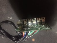
I have an older Chinese made 36 volt 350 watt brushless motor that has suddenly stopped working. I tested the halls supply red/blk and got 6.5 volts but between ground (blk) and yellow blue or green signal wires I got 13.5 volts. One of the halls appears to be facing down, the 2 on the sides up. what would give me such a reading? Is one of the halls open..or since one is facing down, its acting as a voltage doubler? is this normal? You can see in the attached pic that the middle halls 5V is on the end (right side) like its been flipped over and bridged to the rightmost halls, on the normal leftmost lead.
I have ordered the honeywell ss41 as replacements.
also, can one change the cap value on the board to a higher rating to put in more voltage, or is it more involved than that?
and..how does one test the phase wires for output? just put the voltmeter lead in one phase wire hole and the other to ground?
")