brake light wiring

conrad2001

1 µW
Joined
Dec 24, 2019
Messages
2
hi,

Recently, I am looking for a sine wave controller that has a brake light wire.
However, I couldn't find one, so I thought of this way to connect the brake light to an ebrake.
But I'm not sure if I will work fine, can I have some feedback of the circuit below?
thank you
brake light wiring.png
 
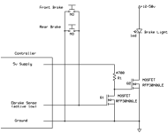
Not really sure how yours would work, is the circled component a relay? Here's what i'm using:

The mosfet can be about any logic-level nchannel within voltage and power rating, such as this.
 
The 5v supply would come from any 5v wire on the controller--throttle power, PAS sensor power, etc.

But it's likely that your original circuit will work, as long as your "low level brake" input on the ocntroller requires grounding it to activate it.

At the least it shouldn't hurt to try it, since the diode should protect the controller input from the battery voltage.


Alternately, if you instead use the high-level brake input, assumign that is activated by battery voltage, then you could simply wire the brake ligth positive to the HL brake input, and the brake light negative to ground (battery negative). Then the brake switch goes from battery positive to the HL brake input.
 
The controller ebrake input has at least 2 wires; ground and a signal line with 5v on it supplied inside the controller by a pullup resister. Some newer controllers have 3 wires, the same 2 wires plus a constant 5v supply line for a hall sensor (for hydraulic brakes). In either case, the front and rear ebrake switches are wired in series and normally closed, so if either one opens, the signal goes from 0 to 5v and triggers the ebrake function. The circuit I showed above uses that same 5v to turn on a mosfet to light up the brake light.
Notice that all the different ebrake switches are used to switch 5v only, so wouldn't count on them being able to handle 48v.
Should also say the the above is for "standard" Chinese controllers, there are no doubt other designs out there...
 
socrace said:
In either case, the front and rear ebrake switches are wired in series and normally closed, so if either one opens, the signal goes from 0 to 5v and triggers the ebrake function.

that's a strange way to wire the system. iv'e never seen this kind if wiring or operation on the ebikes i've worked on or built.

on every controller i've got or used, prebuilt oem bikes or kits or random generic controllers, the ebrake switches are wired in parallel, and are normally open. when the brake lever is pulled, the switch closes, and shorts the signal wire to ground.

the one different style is when a 3-wire brkae switch is used, and it's a hall effect sensor in the brake lever. for these, there's 5v, signal, and ground, but the hall sensor still just grounds the signal line, so a regular brake switch between signal and ground still works.


as far as the voltage rating of the switch, you're likely right, but there are no markings on any of the switches i've ever seen in these ebrake levers, so there's no way to know what their rating actually is without destructive testing. ;)

since there is very little current used, in the milliamp range or less, it's likely that for the original use the voltage would be ok at 48v. but if high current is needed for the brake light, the switch would need to be changed to a different one capble of the higher ovltage and current, or a relay could be used instead, and the relay coil switched by the brake swithc. i've done that myself for such things, like my sb cruiser ligthing, which uses autmotive relays for switching the lighting.

a fet can also be used like you show in your diagram, but would need something else on the switch to change it's grounding function to a 5v output function, like a pnp transistor with it's base to the signal wire, emitter to 5v, and collector to ground and the fet gate input.
 
Yes, another inverting stage like you described would be needed, if the signal line goes to zero to trigger the ebrake!
 
Well, I went down the rabbit hole of trying to find how "standard" Chinese controllers are configured for ebrakes.
Answer from most sellers is: "don't know don't care as long as you buy from me".
So anyway, am now pretty sure amberwolf is right; most ebrake switches are normally open (N.O.), and are wired in parallel.
More generally, any ebrake with a yellow (3 pin) connector is almost certain to have a N.O. switch, and anything with a red (2 pin) connector can be either N.O. or N.C.
Two of the better sources (in addition to amberwolf):
https://www.ebikes.ca/shop/electric-bicycle-parts/ebrakes.html
https://endless-sphere.com/forums/viewtopic.php?t=99277
 
socrace said:
Here's what i'm using:
ebike brake.png
The mosfet can be about any logic-level nchannel within voltage and power rating, such as this.

Is this a working circuit? Would you be kind enough to explain the particulars of how it functions? (learning electronics) Thank you.
 
Hi Tommycat. Yes it's a very simple circuit, although it does work. When the ebrake switch is open, 5v (through a 5k resistor inside the controller) is provided to gate of the mosfet, charging its capacitance, turning it on, and lighting up the brake light. When the ebrake switch is closed, capacitance of the gate terminal is discharged to ground through the switch, to below the mosfet cutoff, turning it off. This particular mosfet is designed to turn on/off at 5v logic levels (below 1.5v off, above 3.5v on). It's a little unusual to turn on a mosfet through such a large gate resistor, because turn on time will be very slow in charging the gate capacitance, but not really a problem given it's power rating.
 
Since you mention brake low,If the controller has wires for both ebrake high and ebrake low, then the ebrake high will take pack voltage down to about 10v (on those I've used). I always use DC/DC converters, because I don't like to run pack voltage on anything going to the handlebars (and high voltage lighting is hard to find), so with a controller that has an ebrake hi I have my brake handles complete the 12v circuit to feed both the brake light and the controller ebrake input...a simple as it gets.
 
Yeah, your method of applying full taillight voltage on the ebrake signal line should be safe, especially at 12-14v max.
12v on the signal input will drop about 7v across the isolation and pullup resistors in parallel to 5v supply, maybe 2 milliamp total, not a problem. But with 52v on the signal input, could be 18 milliamp, risky (and almost enough to turn on the taillight). Just to be sure, could measure the actual draw before applying a big stack voltage to it. Probably best to keep below 5 milliamp I would say.
 
socrace said:
Yeah, your method of applying full taillight voltage on the ebrake signal line should be safe, especially at 12-14v max.
12v on the signal input will drop about 7v across the isolation and pullup resistors in parallel to 5v supply, maybe 2 milliamp total, not a problem. But with 52v on the signal input, could be 18 milliamp, risky (and almost enough to turn on the taillight). Just to be sure, could measure the actual draw before applying a big stack voltage to it. Probably best to keep below 5 milliamp I would say.

No, that's only if the controller is wired for it with an "ebrake hi" input. "Ebrake low" activation is commonly just shorting a signal wire to ground.
 
John in CR said:
so with a controller that has an ebrake hi I have my brake handles complete the 12v circuit to feed both the brake light and the controller ebrake input...a simple as it gets.

What is your total amperage draw thru your brake switch when actuated? Do you know what it is rated at? Thank you.


socrace said:
Hi Tommycat. Yes it's a very simple circuit, although it does work.

But as Amberwolf mentioned earlier, I have what I would consider a "typical" low brake actuation. As in the brake signal is shorted to ground with the brake levers actuated that stops the motor... reverse logic from yours. That said, do you know of a mosfet that would be N.O. with power to the gate, (say about 3.25vdc) which would then close when the gate is grounded? (ovdc) A depletion mode mosfet perhaps? (been doing a little reading.. :wink: ) It sounds like you mentioned a work around in earlier posts, but I can't seem to follow.
 
Seems like over-complicating the simple. Either use one brake handle for brake lights and one for ebrake, or use both for brake lights and a momentary switch like a horn button for ebrake, I've used both. The future is variable force regen, which requires a separate control anyway. You can also step up to a Nucular controller that can do a brake light output when the the ebrake is activated. Plus the Nucs have an ever growing list of user programmable features that you'll never get tire of over-complicating things if that's your thing.

BTW, no idea what the ebrake-low current is on any controller I've ever used, since without a doubt it's lower than the current for a motorcycle brake light flowing through the switch on the brake handle.
 
ebike brake actlow.png
This circuit will allow the taillight to be switched without exposing the ebrake switches or controller sense line to whatever voltage is powering the taillight. It will work with ebrake switches that are wired in parallel as shown (active low). The simpler circuit shown earlier in this post will work with ebrake switches wired in series (active high).
 
Hi socrace,

Now that's what I'm talking about! :thumb:
I see now where the earlier discussion on logic changing fits in, well... OK somewhat.

A few questions if I may.

My brake signal voltage is just 3.06vdc. Will this make the cut? My brake circuit also draws .27mA when grounded if this matters.

I see the 4700 ohm resistor cuts the possible amp draw to 1mA (milliamp), with the specs on the gate current @ less than 250 microamps? Just checking to see if I'm getting this right. Not use to working with such small values.

I like the separation of the high voltage to the low voltage control. And it looks like there is no way around adding the 5vdc control circuit...

The getting two of the same component is a nice touch also, (mosfets) and probably simplifies it a bit.

But as an added exercise could a PN2222 transistor be used for the lowest voltage switch? (have on hand) Are transistors actuated by current verses voltage? And would a resistor in line be required?

But I would certainly like to thank you for all your efforts! Well done! I've been trying to solve this puzzle for some time, and certainly appreciate your input and expertise.

Have a happy new year!
Cheers! :)
 
FWIW I think the OP’s original diagram in the first post would work fine. You could add a small fuse in series with the B+ line to protect against shorts.
 
I agree with Fechter, as long as the signal line is active low, the ebrake switch can handle the taillight load, and the controller is using 5v not 3.3v logic levels. The 1N4007 will likely have too much forward voltage drop for 3.3v. But looks like OP has access to spice, if so you can model the ebrake input with a simple 5k pullup to logic voltage.
TommyCat, thanks. Sounds like your controller may be using 3.3v ebrake logic levels. Both schematics above should still work ok at 3.3v. I think the 2n2222 will need too much base current to turn on, and will affect the controller ebrake function.
 
Roger that.

With a circuit amperage of .27mA at 3.3vdc when the logic signal is grounded. Can I speculate that a 10k pull-up resistor is used? And thus use that for testing? Or stick with 5K.

I will be testing with a breadboard first. Spice looks wayyyy over my head, if even installable. :shock: Anyone use Circuit Lab?

Anyone know what a typical Ebike brake lever switch is rated at?

Last chance at a mosfet used in a reverse logic (N.C.) circuit... IE: contacts open with power to the gate...
 
TommyCat said:
Anyone know what a typical Ebike brake lever switch is rated at?

no, but iv'e put up ot a few amps plus them, at 12-16v, for my old incandescent brake light setups, and never had even the crappiest ones fail from that. (they did fail from water ingress, or simply disintegrate mechanically, etc., but not electrically).

similarly, the cheap switches in the little turn signal / 3speed switches that mount on handlebars for ebikes have worked fine for years, even with incandescent lamps.

my led lighting presently used is only an amp or two.

since it's not usually on for more than a few seconds at a time, it's not that big a deal. if you are sitting at a traffic light for minutes at a time, and drawing many amps, that might indeed be a prblem--but it's more likley to be an issue with the tiny wires inside the cabling to the switch than it is the siwtch itself. ;) (which can be as small as only two or three very thin strands of conductor inside the insulation)


you would have to do a test-to-destruction on any particulare swithc to find out what it's actual failure point would be. but i would say that a couple of amps is a safe enough limit.
 
Back
Top