Sabvoton 72150 phase testing, no combination works

darkmunk

10 mW
Joined
Apr 13, 2020
Messages
33
Location
Plymouth
I have a Sabvoton 72150 and an Evolution moped hub motor with no information except 3kw, 72v, 60 phase angle.
I bought a usb cable and a bluetooth dongle for the Sabvoton.
I hooked up to both quite easily. I used the dongle and Mqcon app to run 36 phase wire tests, and the closest I got to a rotating wheel, was a slow creep for about 20 degrees before the usual 'hall error'.
I usually used 10 or 15 amps as the test current. I did try 30 amps a couple of times but it made no difference.
It says offset angle is 54 degrees. this never changes.
Haven't noticed anywhere to change the phase angle.
I don't know what ' motor parameter' means. It stays on 300.

Is it possible my new controller is a bad one?
I simple can't find any combination that does any more than twitch the wheel, either forward or backward a few degrees before stopping with hall error. Quite loudly sometimes. Occasionally it seems to just jam. I would expect all these scenarios at some point in the process, but also one or two that actually turn the wheel, but the controller just stops after each twitch and shows me 13 green lights. The app shows hall fault.
I switch the controller off and back on and either move the wheel to try again or try a different combination.
I have the white (temperature?) wire in the phase block, grounded with 1k ohm resister as the motor doesn't appear to have a temp sensor.

The motor is fine and works beautifully when I re-instate the old controller, but it's restricted, so it has to go.

Going mad now! been weeks of fiddling and nothing :(
 
Maybe your old controller can work in sensorless mode and halls are faulty indeed. Or maybe halls partially broken and your old controller can work with it and Sabvoton can not. I'm saying because I know you tried various phase and hall combinations. I hope your tried correct ones.
Even with correct combination I used to get hall error during testing, particularly with my scooter's big hub motor. Nevertheless after second or third try test was passing OK and motor running good with Sabvoton.

See how to test hall on youtube or:
Plug 'controller hall connector' to 'motor hall connector' as usually.

''+5v'' and ''-'' feeds halls inside motor (thin red and black wires).

Insert your voltmeter "black"probe to "-" inside hall connctor.
Insert your voltmeter "+" probe to green, yellow, blue halls connectors respectively.
Slowly turn by hand wheel and see if voltmeter shows 0v,5v,0v,5v,0v,5v,0v ...

I doubt your halls are faulty but we have go testing everything because you tried various phase wire combinations.

Regarding that number - 300. I never changed it and it worked with various motors.
offset angle is determined by controller itself therefore your don't need to input this number yourself.

One more thing to have in mind. Hall test would fail if there is resistance when doing test, for eq if brake pads are touching brake rotor, some broken or old bearing, or chain which tries to spin pedals when wheel spins reverse! You can set higher amps doing testing, but you tried 30a which is high enough.
 
Ah that's excellent advice, thank you.
The wheel does feel a little stiff. I backed off the brake yesterday, but it still doesn't spin very freely.
So maybe I can try higher amps?
I'll go and do that hall test right now...
 
I've tried high amps, for 50A for test and it worked for me the same as 15A. So I think yes, you can trie high amps.
 
OK, I've done a hall test as suggested. See video:
[youtube]https://youtu.be/eWWdIhVt_9Y[/youtube]
I've probably done something stupid, but none of the halls gives 5v back as I turn the wheel slowly.
As the moped works perfectly with the old controller, and I'm getting nothing back from any of the hall wires, I'm wondering if the motor even has halls?
 
Incidentally, If I switch on the controller and get no errors, then turn the wheel slowly, its green LED shows a hall error. This suggests the hall wires are indeed connected to hall sensors and the controller is getting signals from them, and throwing an error.
 
I watched your video several times trying to figure out where is the catch, why there is no any output signal from any three halls ie yellow,blue,green signal wires.

One thing pop up into my mind. Why to supply black/ground ("-") to controllers halls connector. You can supply "-" straight from your external power supply to motors halls black "-" wire. Nevertheless it should not make difference because you used crocodile to transfer ground to hubs halls ground wire. I wonder why none of halls gives any ~+5v. Seems that all three halls are fried.

I want second or third opinion from before suggesting you to open the motor and watching at halls inside.

Watch this https://www.youtube.com/watch?v=efYFOHnXh0E
but looks you done test little bit differently but correctly. Can you test plugging your probes to controller before you get errors inside controller. Because you mentioned you get hall error after once you move wheel if I understood correctly your last post.
Spin your wheel reeeaaally slow, maybe multimeter does not quick enough to react to 5v,0,5v,0etc.
 
BTW I searched your old controller in internet to find out if its sensored or sensorless or both but can't find it.
Not long ago I had some motor with faulty hall(s). When connecting it to Sabvoton I would get "hall error" without needed to touch/spin hub motor. I did this controller connect/disconnect and spin little bit wheel, several time and always would get hall error straight away without needing to spin (move) wheel (hub) little bit.
 
Thanks for taking the time to watch the video several times :)
Yes, I just left the ground in place, but removed all the others to avoid any strange signals.
I also tried it using power from the controller. It delivered 5v to the halls, but nothing came back. Not a flicker.
I moved the wheel really slowly.
The old controller seems to have almost identical wiring, including a block of five hall connector wires, no apparent temperature wire. All sorts of unused wires just like the sabvoton (in my installation). But colours don't match of course. So, again, it does seem to depend on hall sensors, rather than being a senseless controller.
 
So for the sake of accuracy, I've done the hall test again, this time with minute movements of the wheel instead of just slow, and the multimeter set to millivolts and the most I saw on the yellow was 128mV, more normally the flicker would be around 50 mV.
So there do appear to be halls present, but very sketchy ones!
I think if I'm testing them properly, and this is as good as they give, then the Sabvoton would be forgiven for claiming they're faulty and giving up.
 
Yes, seems broken halls.
The strange thing is that all three are broken instead only one.
 
Is it possible I cooked them ?
Still doesn't explain why it works fine with the old controller though eh?
I'll have to put the old one back in again. Got to get to work on something ;)
 
It can be that old controller is sensorless.

Halls can be cooked by static charges or when (if) it connected to phase wires accidently.
 
I put the old controller back and everything works fine.
I want to buy some new halls anyway. I’ve read it can help to get good quality halls. Smoother running etc.
Do i need to dig the old ones out, rendering my transport useless for a while? Or can i makd sn educated guess?
I assume I need a digital 0 - 1 style, rather than analogue (progressive)?
 
I put the old controller back and everything works fine.
I want to buy some new halls anyway. I’ve read it can help to get good quality halls? Smoother running etc.
Do I need to dig the old ones out, rendering my transport useless for a while? Or can i make an educated guess about the required components?
I assume I need a digital 0 - 1 style, rather than analogue (progressive)?
 
Don't go changing hall sensors until you prove it's actually a sensor problem and not a wire problem, broken or shorted.

Also, make sure your Sabvoton is compatible with a 60° angle motor, since 120° is almost the de facto standard for hubmotors out of China.
 
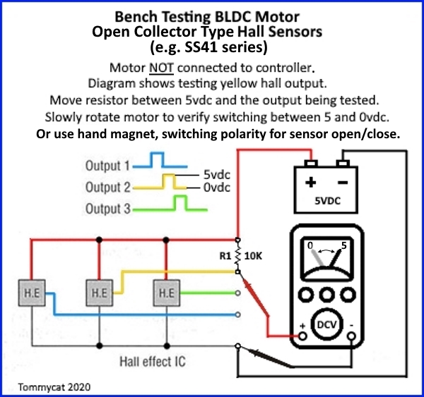
If you don't have a pullup from the hall signal to 5v (this is built into the controller) you won't get a 5v output from them. The halls in most ebike motors simply ground their outputs when they are "on".

This means that the 5v pullup (1k-10kohm resistor from signal to 5v) provides an always-5v-signal, which the hall grounds to nearly 0v whenever it's turned on by a magnet.

No pullup means no changing signal as magnets pass.
 
That said...it's not uncommon for kelly and sabvoton controllers to report problems reading hall sensors that are perfectly good and work fine on other controllers.

Sometimes the issue has nothing to do with the hall sensors, and is some completley different problem, and is not actually anything to do with reading the halls or a hall test, even though the program tells you it is. (badly written software)

One possible search:
https://endless-sphere.com/forums/search.php?keywords=sabvoton+hall*&terms=all&author=&sc=1&sf=titleonly&sr=topics&sk=t&sd=d&st=0&ch=300&t=0&submit=Search
 
Have you tried pre setting the hall angle before you start the test, this often solves the problem. IE: some QS205 motors like 15 degrees too get the test to work.
 
Thanks guys.
I can't find the purchase correspondence (dead mac) but phase angle is the first thing I would have checked and asked about. I swapped several emails with China before I bought it. Do they make different versions?
I can't find anywhere in the software to input phase angle, so maybe it's not compatible with 60 and it was mis-sold? :roll:
Regarding the pull-up voltage; do I have to put a resistor across the terminals if they're not attached to the controller (for testing)?
If it is able to handle 60 degrees and my halls are upsetting it, is there any way to make the controller ignore the problem? It seems to stop as soon as it decides there's a fault.
 
Jonno said:
Have you tried pre setting the hall angle before you start the test, this often solves the problem. IE: some QS205 motors like 15 degrees too get the test to work.
I haven't tried 15. I'll try that next time. Thanks.
 
it's on the debug page where you start the test.
 
darkmunk said:
Regarding the pull-up voltage; do I have to put a resistor across the terminals if they're not attached to the controller (for testing)?

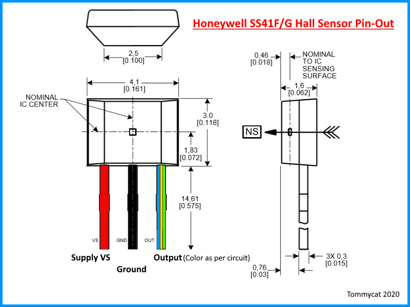
Yes... these may help.


NktFBwJ.jpg


dAAKziF.png
 
Back
Top