* * * MOTOR UNIVERSITY (Lab 101) * * *

safe

1 GW
Joined
Dec 22, 2006
Messages
5,681
This thread will go through the process of how electric motors work and how to model their behavior in a spreadsheet. I'm going to go through EVERYTHING starting from the very beginning and all the way through to advanced topics. The idea is that you will be able to use the spreadsheets much like you might use other types of "tools" in a lab class.

This series of classes will take time to work through and I'm going to do my best to pace the courses at a rate that most people seem able to follow. Questions along the way will likely slow things down, but that's how people learn by asking questions about what they can't understand.

Please... let's all behave as "adults" and not spoil the class for those that might really want to learn. Please keep your questions to the actual topic being discussed and keep yourself from disruptive behavior. We just don't need it. Really!

:arrow: Be on your "best behavior"!!!

So we begin... :)

This posting has been edited and now it holds the "Motor University Lessons" in either Excel format or the old Works format where they were created. Both zip files have the images for the Lessons too.
 

Attachments

  • Motor University Lessons in Excel Format.zip
    226 KB · Views: 131
  • Motor University Lessons in Works Format.zip
    177.5 KB · Views: 122
Lesson 1

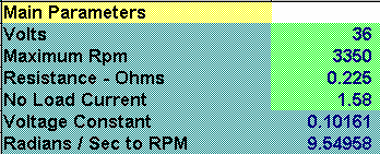
First let's look at the "Main Parameters" that any motor will need in order to model their behavior. This particular motor is a close approximation of the Unite 36 Volt motor. You will in the near future have the freedom to play around with these parameters and see what happens. The light green parameters are configurable. The dark green parameters are constants (Radians / Sec to RPM) or are derivative of other parameters. (Voltage Constant)

:arrow: At this point are there any questions about what we are starting with?
 

Attachments

  • Lesson 01.gif
    Lesson 01.gif
    4.4 KB · Views: 4,649
safe said:
Lesson 1


:arrow: At this point are there any questions about what we are starting with?

1) At what rpm is the No Load current ?

2) Units please Mr Teacher !!
 
Data Points

In order to divide a problem for a spreadsheet (or any other way) you typically decide on certain number of "Data Points" that will become the shape of the resulting curves for you motor. The more data points the higher the precision. In this case I've decided to use 100 data points because it's a nice number that divides well.

RPM

If you know the maximum rpms that a motor can spin in it's "no load" state then you can divide that value by the number of data points. From this you can establish how many rpms you have for each data point. This is simply laying the foundations for the spreadsheet.

BackEmf

http://en.wikipedia.org/wiki/Back_emf

The only thing that NEVER changes with a motor is it's "Back EMF". (at least the controller can't change anything about it) It's called a "Back EMF" because the permanent magnets in the motor tend to resist the motor wanting to spin. The faster the motor spins the higher the "push back" that you get. The equation that defines the "BackEmf" is simple and linear:

= VoltageConstant * ( Rpm / RadiansSec )
 
eP said:
1) At what rpm is the No Load current ?

The "No Load" current is defined as the current in Amps required to spin the motor at it's "Maximum Speed" in rpms. This is the second parameter. (two above the "No Load" parameter)

Before we can go much further we will need the "study guides" to be converted into "excel" so that we can use them. So we might be done for now until that is completed.

We're in no hurry...
 
With a brushless motor you can change the BEMF by changing the phase of the switching, easily done with a microprocessor controlled driver. For a brushed one you can do the same by swinging the brushes round a bit, a bowden cable to the handlebars?
 
maxwell said:
With a brushless motor you can change the BEMF by changing the phase of the switching, easily done with a microprocessor controlled driver. For a brushed one you can do the same by swinging the brushes round a bit, a bowden cable to the handlebars?

For this case we're going to use a simple brushed motor without any "advanced" topics. We're starting from the "beginning" and going forward. Save those questions for later... (good point though)

I've got to do my grocery shopping, so I'll have to answer later... I just want to get those "study guides" converted before getting too deep into this...
 
safe said:
I just want to get those "study guides" converted before getting too deep into this...

Done.

:D
 

Attachments

  • SafesLesson.xls
    35 KB · Views: 202
Well thats cleared up the "NEVER" to a "NEVER IN THIS CASE" I must make a dyno so I can test my new controller with it's phase advance feature and get some results for a 408.
 
maxwell said:
Well thats cleared up the "NEVER" to a "NEVER IN THIS CASE" I must make a dyno so I can test my new controller with it's phase advance feature and get some results for a 408.

I just dug out my treadmill to make a dyno out of it.

There must be a way to calibrate differing systems, so results are universally meaningful. I haven't figured that out yet.

Do you think your controller would work with a brushless outrunner-motor? (Fechter mentioned they are sensorless.)

:?
 
TylerDurden said:

Thanks for converting those. :) (how "adult" of you)

Let me remind everyone that this is not the place to be asking questions that are not related to the "study material". If you've got some advanced theories that you are toying around with (like the advancing of the magnets to tinker with the BackEmf) then you need to create your own threads for that.

:arrow: Please... for the sake of people who might want to learn, but just don't want to get into posting out of fear of looking unknowledgeable let's keep this a very "tight" course about motors.

Thanks again...
 
Okay... it looks like we have the "study material" available in a format that everyone can access. (well, at this point no, but eventually yes)

Let's proceed...

If you look at the Lesson 01.xls (or .wks) spreadsheet you will have the "Main Parameters" in the upper left and the "Data Points", "RPM", and "BackEmf" across the middle running all the way out to 100 data points.

If there are any questions about this please ask... I suspect we are more or less finished building the "framework" and can move on to "Lesson 2".

Feel free to ask any question though... really... :)
 
Lesson 2

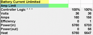
So far all we've done is created the boundries in which the motor data will be placed. We've essentially created the "slots" in which the formulas will be applied. Now it's time to move on to the charactoristics of an electric motor itself. I'm going to begin with the image for this lesson which shows by name the various entities that we will master about the motor.

:arrow: Be patient, we will go through each element one at a time.

For this first case we will not be using "Controller Logic" that is in any way sophisticated. In fact, for this first case we are using an "unlimited controller" which basically means you connect the battery directly to the motor and watch it go from zero to maximum rpms. We will get to the more sophisticated controller logic in the later lessons.
 

Attachments

  • Lesson 02.gif
    Lesson 02.gif
    5.4 KB · Views: 4,565
Am I the first to look at the study material that Tyler converted? LOL

Greg
 
gwsaltspring said:
Am I the first to look at the study material that Tyler converted? LOL

Greg
In the true sense that in class, a student offers to help the teacher and then puts a "kick me" sign on back. It makes everyone laugh until the teacher finds out. It might be warrant to have them "really" converted since it seems a lot of people are at least reading them or the "prank" ones anyway.
 
Duty Cycle and the Controller Logic

When we talk about a controller we have to introduce another idea which is the "duty cycle". The term "duty cycle" is a little strange and at first I was resistant to using it, but it is the convention in the industry so at some point you will be forced to make it part of your vocabulary. What this means is the "percentage of time that the controller allows it's battery voltage to pass through to the motor". Things will get much more complicated later as we get into discussions of how things "come out the other side", but for now just think of it as a percentage. A low percentage means that less voltage passes through. A high percentage (up to 100%) means that most of the voltage available passes through.

In this lesson we are using a constant value of 100% "duty cycle" which means that the controller is just a wire connecting the battery to the motor.

You can't get much less complicated controller logic than a simple wire! :lol:
 
knightmb said:
It might be warrant to have them "really" converted since it seems a lot of people are at least reading them or the "prank" ones anyway.

Anyone want to "really" convert them?

There are people that might actually want to learn something... :roll:
 
safe said:
knightmb said:
It might be warrant to have them "really" converted since it seems a lot of people are at least reading them or the "prank" ones anyway.

Anyone want to "really" convert them?

There are people that might actually want to learn something... :roll:
I would if I had anything that could. The *.wks being the old Microsoft Works format?
 
Volts

The "Volts" of the motor are a simple calculation. As mentioned previously in the "duty cycle" posting you can arrive at the voltage that the motor sees by multiplying the "duty cycle" by the battery voltage.

:arrow: So we get:

Volts = ( Controller Logic for Duty Cycle ) * ( Battery Voltage )
 
knightmb said:
I would if I had anything that could. The *.wks being the old Microsoft Works format?

Yeah... this has been a problem a few times. I've got an old version of Windows 98 and it's got Works on it. I hear that "Open Office" will convert them. Don't worry, eventually someone will contribute... there's no hurry and I will eventually repackage the entire thing after it's all done. So don't worry... this will go on for days... and will get "cleaned up" in the end. (after it's all done)
 
safe said:
So don't worry... this will go on for days... and will get "cleaned up" in the end. (after it's all done)
[/b][/color][/size]

If you would like your spreadsheet errors corrected, you should do it yourself.

Trying to con more educated people to do it for you, under the guise of teaching curious people is pathetic.

Anyone seeking more information about motors should find a qualified source, perhaps someone with a real degree.
 
Thanks to Maxwell for contributing such an important fact for those of us just beginning to learn about motors. His enthusiasm is contagious and I don't know how I could ever have learned about motors without first knowing how to manipulate back emf through phase advance.

Tyler's sense of civic obligation is exemplary even if his xcel skills aren't. Jokes are funny if you know when and how to tell them.

Good work, guys! You are a credit to Endless Sphere.

I hope these files work for those who are interested.
 
Amps (Current)

The current that flows through a motor is defined by only two variables:

:arrow: The first limitation is the "BackEmf" which is tied to motor rpms. So at low rpms the amount of "negative push" we get from the motor is low. As the motor rpms increase we get more and more "negative push" until the limit of the motor is reached and the voltage applied to move the motor faster has run out. We have reached the "no load" speed when this occurs.

:arrow: The second limitiation is the voltage that is "applied" to the motor at any given rpm. In this lesson we are using a "duty cycle" of 100% all the time (like a wire) so the battery voltage and the "applied" voltage are the same, but in other "real world" controllers the "duty cycle" varies depending on it's specific "controller logic".

So we can arrive at a simple formula to define the motor current:

Amps (current) = ( ( Volts "Applied" ) - ( BackEmf ) ) / Resistance

You see that I'm introducing another factor here which is the Resistance. The Resistance of the motor is important in determining the current because:

Current = Volts / Resistance

or the more familiar:

Volts = Current * Resistance

...motor resistance is not really a variable unless you want to include motor heating into your equations in which case it does become variable. For this lesson we are using a "simple" constant value for motor resistance. But you can log that away in the back of your mind as another important "hidden factor" that effects motor performance. :wink:
 
silentflight said:
I hope these files work for those who are interested.

Thanks. I really can't even open the files myself so I'll just assume they are correct. If someone really wants to learn they deserve the right to access the source material.
 
Back
Top