stancecoke
100 kW
- Joined
- Aug 2, 2017
- Messages
- 1,811
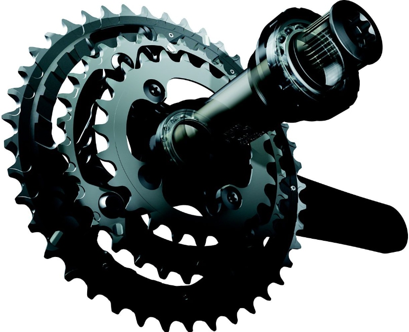
This topic has been driving me around for a while. All commercially available bottom bracket torque sensors are for square taper or Isis cranks. Today's "standard" in the upper class, however, is Hollowtech II.
Building on the v5 sensor, I worked with @arozhkov2001 to develop a sensor that works with a Hollowtech II bottom bracket. Thanks also to @bjp for providing me with a Hollotech II bottom bracket set! :thumb:
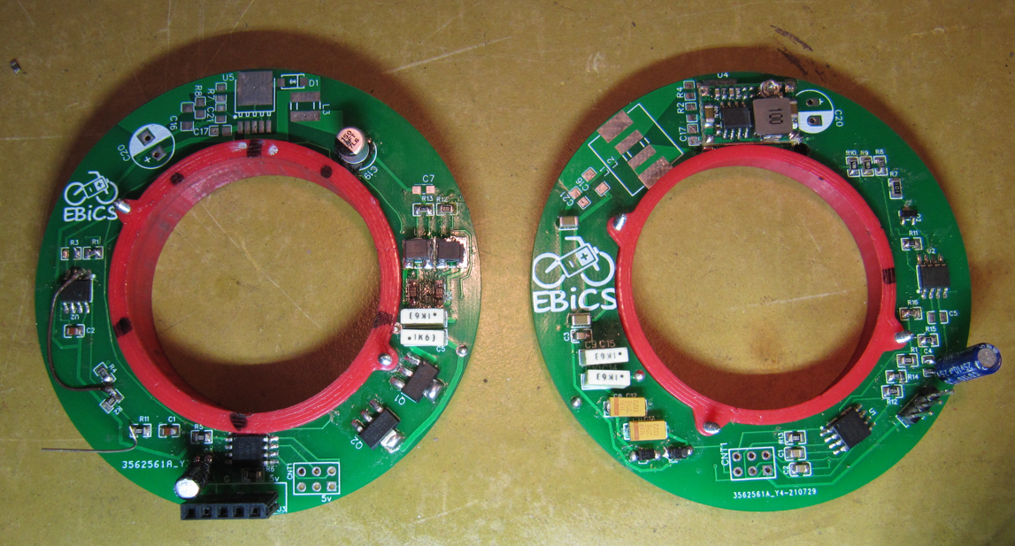
Energy is transmitted wirelessly from the frame-mounted transmitter to the co-rotating receiver via a pair of coils.
Strain gauges on the crank arm detect the torque. The strain gauge signal is amplified by an opamp and transformed by an ATTiny85 into a square wave signal whose frequency is proportional to the torque. This square wave signal is given to three parallel IR-LED. These light pulses on receiver side are received on transmitter side by means of five parallel IR photodiodes and again converted into an analog voltage signal by an ATTiny 85, so that the signal provided is the same as known from Sempu, E-Rider, etc.
The arrangement of the transmit and receive LEDs is such that a PAS signal is generated simultaneously with the torque signal.
Currently I measure only as a half-bridge from one crank, but because the bottom bracket shaft, as the name Hollowtech already says, is hollow, it is also no problem to lay a cable to the other side of the frame and measure with a full bridge from both cranks 8).
In the video you can see the setup on the workbench and the square wave signal received on the transmitter side, whose frequency changes with the applied torque.
[youtube]qrtE9SNAHxg[/youtube]
I designed the circuits on transmitter and receiver side, @arozhkov2001 made the PCB layout. We ordered the boards from JLCPCB in China.
One drawback is the relatively high current consumption of about 500mA@5V. This can certainly be improved with a ferrite foil for shielding to metallic neighboring components and inductors with lower internal resistance. But it works like this for the time being!")
The sensor is not much bigger than a 12 magnet PAS disc and fits on the left pedal crank. The transmitter clamps on the rim of the bearing shell, the receiver is currently guided in the housing of the transmitter, in a professional solution, the receiver could be firmly cast on the crank and then work completely contactless to the transmitter.
The schematics and bascom code for the transmitter and receiver side can be found at github:
https://github.com/EBiCS/EBiCS_Hollowtech_TorqueSensor
For more photos, see the german forum:
https://www.pedelecforum.de/forum/index.php?threads/prototyp-drehmomentsensor-f%C3%BCr-hollowtech-ii-eigenbau-v6.92119/post-1765834
regards
stancoke
Translated with www.DeepL.com/Translator (free version)
Building on the v5 sensor, I worked with @arozhkov2001 to develop a sensor that works with a Hollowtech II bottom bracket. Thanks also to @bjp for providing me with a Hollotech II bottom bracket set! :thumb:
Energy is transmitted wirelessly from the frame-mounted transmitter to the co-rotating receiver via a pair of coils.
Strain gauges on the crank arm detect the torque. The strain gauge signal is amplified by an opamp and transformed by an ATTiny85 into a square wave signal whose frequency is proportional to the torque. This square wave signal is given to three parallel IR-LED. These light pulses on receiver side are received on transmitter side by means of five parallel IR photodiodes and again converted into an analog voltage signal by an ATTiny 85, so that the signal provided is the same as known from Sempu, E-Rider, etc.
The arrangement of the transmit and receive LEDs is such that a PAS signal is generated simultaneously with the torque signal.
Currently I measure only as a half-bridge from one crank, but because the bottom bracket shaft, as the name Hollowtech already says, is hollow, it is also no problem to lay a cable to the other side of the frame and measure with a full bridge from both cranks 8).
In the video you can see the setup on the workbench and the square wave signal received on the transmitter side, whose frequency changes with the applied torque.
[youtube]qrtE9SNAHxg[/youtube]
I designed the circuits on transmitter and receiver side, @arozhkov2001 made the PCB layout. We ordered the boards from JLCPCB in China.
One drawback is the relatively high current consumption of about 500mA@5V. This can certainly be improved with a ferrite foil for shielding to metallic neighboring components and inductors with lower internal resistance. But it works like this for the time being!
The sensor is not much bigger than a 12 magnet PAS disc and fits on the left pedal crank. The transmitter clamps on the rim of the bearing shell, the receiver is currently guided in the housing of the transmitter, in a professional solution, the receiver could be firmly cast on the crank and then work completely contactless to the transmitter.
The schematics and bascom code for the transmitter and receiver side can be found at github:
https://github.com/EBiCS/EBiCS_Hollowtech_TorqueSensor
For more photos, see the german forum:
https://www.pedelecforum.de/forum/index.php?threads/prototyp-drehmomentsensor-f%C3%BCr-hollowtech-ii-eigenbau-v6.92119/post-1765834
regards
stancoke
Translated with www.DeepL.com/Translator (free version)